Braun Corporation FMVSS No. 403 Quick Reference Installation Sheet 31312
5 | ,IMITM3WITCH !DJUSTMENT |
2%15)2%$ "92&%$%2!,",!7
6 | |
|
|
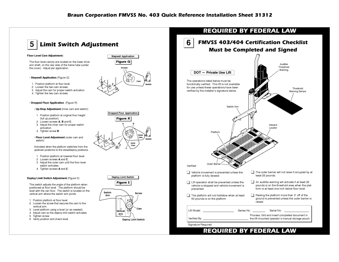
Floor Level Cam Adjustment:
The floor level cam(s) are located on the lower drive arm shaft, on the rear side of the frame tube (under the cover). Adjust per application.
• Stepwell Application (Figure Q) | ||
1. | Position platform at floor level. | |
2. | Loosen the two cam screws. | |
3. | Adjust the cam for proper switch activation. | |
4. | Tighten the two cam screws. | |
• Dropped Floor Application (Figure R) | ||
| • | |
| 1. | Position platform at original floor height |
|
| (full up position). |
| 2. | Loosen screws A, B and C. |
| 3. | Adjust the inner cam for proper switch |
|
| activation. |
| 4. | Tighten screw B. |
Stepwell Application
&IGUREE1 

Screws
Cam
Dropped Floor Application ![]()
&IGUREE2 |
|
A | B |
![]() Switch
Switch
DOT — Private Use Lift
The operations listed below must be functionally verified. This lift is not available for use unless these operations have been verified by the installerʼs signature below.
Switch Arm
Platform
Audible
Threshold
Warning
Threshold
Warning Sensor
Inboard
Locator
• Floor Level Adjustment (outer cam and |
switch): |
Activated when the platform switches from the up/down positions to the stow/deploy positions.
1.Position platform at lowered floor level.
2.Loosen screws A and C.
3.Adjust the outer cam until the floor level switch activates.
4.Tighten screws A and C.
C
Outer ![]()
Cam
Inner
Cam ![]()
Switch
Verified: | Outer Barrier |
|
Deploy Limit Switch Adjustment (Figure S)
This switch adjusts the angle of the platform when positioned at floor level. The platform should be level with the van floor. The switch is located on the
Deploy Limit Switch
&IGUREE3 

Vehicle movement is prevented unless the platform is fully stowed.
Lift operation shall be prevented unless the vehicle is stopped and vehicle movement is prevented.
The outer barrier will not raise if occupied by at least 25 pounds.
An audible warning will activate if at least 25 pounds is on the threshold area when the plat- form is at least one inch below floor level.
vertical arm where the switch arm pivots.
1. | Position platform at floor level. |
2. | Loosen the screw that secures the cam to the |
| vertical arm. |
Switch
Arm
Screw
The platform will not fold/stow when at least 50 pounds is on the platform.
Raising the platform more than 3” off of the ground is prevented unless the outer barrier is raised.
3. | Level platform using a level (or as needed). |
4. | Adjust cam so the deploy limit switch activates. |
5. | Tighten screw. |
Vertical
Arm
Lift Model: |
| Series No: |
| Serial No: |
|
|
| Process, fold and insert completed document in | |||
6. Verify position and check level. |
Deploy Limit Switch
Verified By: |
| the |
Signature Required
2%15)2%$ "92&%$%2!,",!7