Braun Corporation FMVSS No. 403 Quick Reference Installation Sheet 32553 Rev. A
3 |
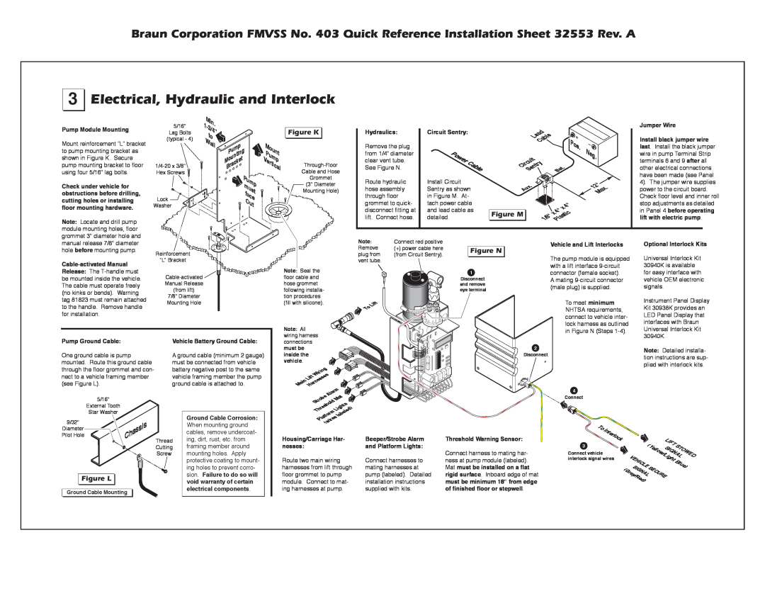
Electrical, Hydraulic and Interlock
Pump Module Mounting
Mount reinforcement “L” bracket to pump mounting bracket as shown in Figure K. Secure pump mounting bracket to floor using four 5/16" lag bolts.
Check under vehicle for obstructions before drilling, cutting holes or installing
5/16"
Lag Bolts
(typical - 4)
![]()
Lock
Min. |
|
1- |
|
3/4” |
|
to |
|
Wall | Pump |
| |
| Mounting |
| Bracket |
Pump
must
face
Out
Mount
Pump
Vertical
Figure K ![]()
![]()
Cable and Hose
Grommet
(3" Diameter
Mounting Hole)
Hydraulics:
Remove the plug from 1/4" diameter clear vent tube. See Figure N.
Route hydraulic hose assembly through floor grommet to quick-
Circuit Sentry:
Power | Cable |
|
Install Circuit Sentry as shown in Figure M. At- tach power cable
Lead |
|
Cable |
|
Circuit | . |
try |
|
Sen | Bat |
. |
|
Aux |
|
Pos.
Neg.
12" . Max
Jumper Wire
Install black jumper wire last. Install the black jumper wire in pump Terminal Strip terminals 6 and 9 after all other electrical connections have been made (see Panel
4). The jumper wire supplies power to the circuit board. Check floor level and inner roll
floor mounting hardware.
Washer
disconnect fitting at lift. Connect hose.
and lead cable as detailed.
|
|
|
| 4" |
|
|
| x | |
Figure M |
| 4" |
| |
x | stic | |||
1/8" |
| |||
| Pla |
| ||
|
| |||
stop adjustments as detailed in Panel 4 before operating lift with electric pump.
Note: Locate and drill pump module mounting holes, floor grommet 3" diameter hole and manual release 7/8" diameter hole before mounting pump.
Reinforcement
“L” Bracket
Note: | Connect red positive |
| |
Remove | (+) power cable here |
| |
Figure N | |||
plug from | (from Circuit Sentry). | ||
|
vent tube.
Vehicle and Lift Interlocks
The pump module is equipped
Optional Interlock Kits
Universal Interlock Kit
Release: The
![]()
Manual Release
(from lift)
7/8" Diameter
Mounting Hole
Note: Seal the |
|
floor cable and |
|
hose grommet |
|
following installa- |
|
tion procedures |
|
(fill with silicone). | Lift |
| |
| To |
Note: All |
|
wiring harness |
|
1 Disconnect and remove eye terminal
with a lift interface
To meet minimum NHTSA requirements, connect to vehicle inter- lock harness as outlined in Figure N (Steps
30940K is available for easy interface with vehicle OEM electronic signals.
Instrument Panel Display Kit 30938K provides an LED Panel Display that interfaces with Braun Universal Interlock Kit 30940K.
Pump Ground Cable:
One ground cable is pump mounted. Route this ground cable through the floor grommet and con- nect to a vehicle framing member (see Figure L).
Vehicle Battery Ground Cable:
A ground cable (minimum 2 gauge) must be connected from vehicle battery negative post to the same vehicle framing member the pump ground cable is attached to.
connections |
|
must be |
|
inside the |
|
vehicle. |
|
Wiring | |
Lift | es |
MainHarness | |
| m |
| lar |
| A |
2
Disconnect
4
Note: Detailed installa- tion instructions are sup- plied with interlock kits.
5/16" |
External Tooth |
Star Washer |
9/32" |
Ground Cable Corrosion:
When mounting ground
Strobe | Mat |
shold | |
Thre | Lights |
tform labeled) | |
Pla | res |
(wi | |
Connect
Diameter | Chassis |
|
Pilot Hole | Thread | |
| ||
|
| |
|
| Cutting |
|
| Screw |
Figure L ![]()
![]()
Ground Cable Mounting
cables, remove undercoat- ing, dirt, rust, etc. from framing member around mounting holes. Apply protective coating to mount- ing holes to prevent corro- sion. Failure to do so will void warranty of certain electrical components.
Housing/Carriage Har- nesses:
Route two main wiring harnesses from lift through floor grommet to pump module. Connect to mat- ing harnesses at pump.
Beeper/Strobe Alarm and Platform Lights:
Connect harnesses to mating harnesses at pump (labeled). Detailed installation instructions supplied with kits.
Threshold Warning Sensor:
Connect harness to mating har- ness at pump module (labeled). Mat must be installed on a flat rigid surface. Inboard edge of mat must be minimum 18" from edge of finished floor or stepwell.
To | Interlock |
|
|
|
|
|
|
|
|
| LIFT |
| |
interlock signal wires |
|
|
|
| ||
|
|
| (Yellow/Light | S | ||
3 |
|
|
|
|
| |
Connect vehicle |
|
| VEHICLE | SIGNALTOWED | ||
|
|
|
| |||
|
|
|
| Blue) | ||
|
| (Gr | SIG | NALSECURE |
| |
|
|
| ey/Red) |
|
| |