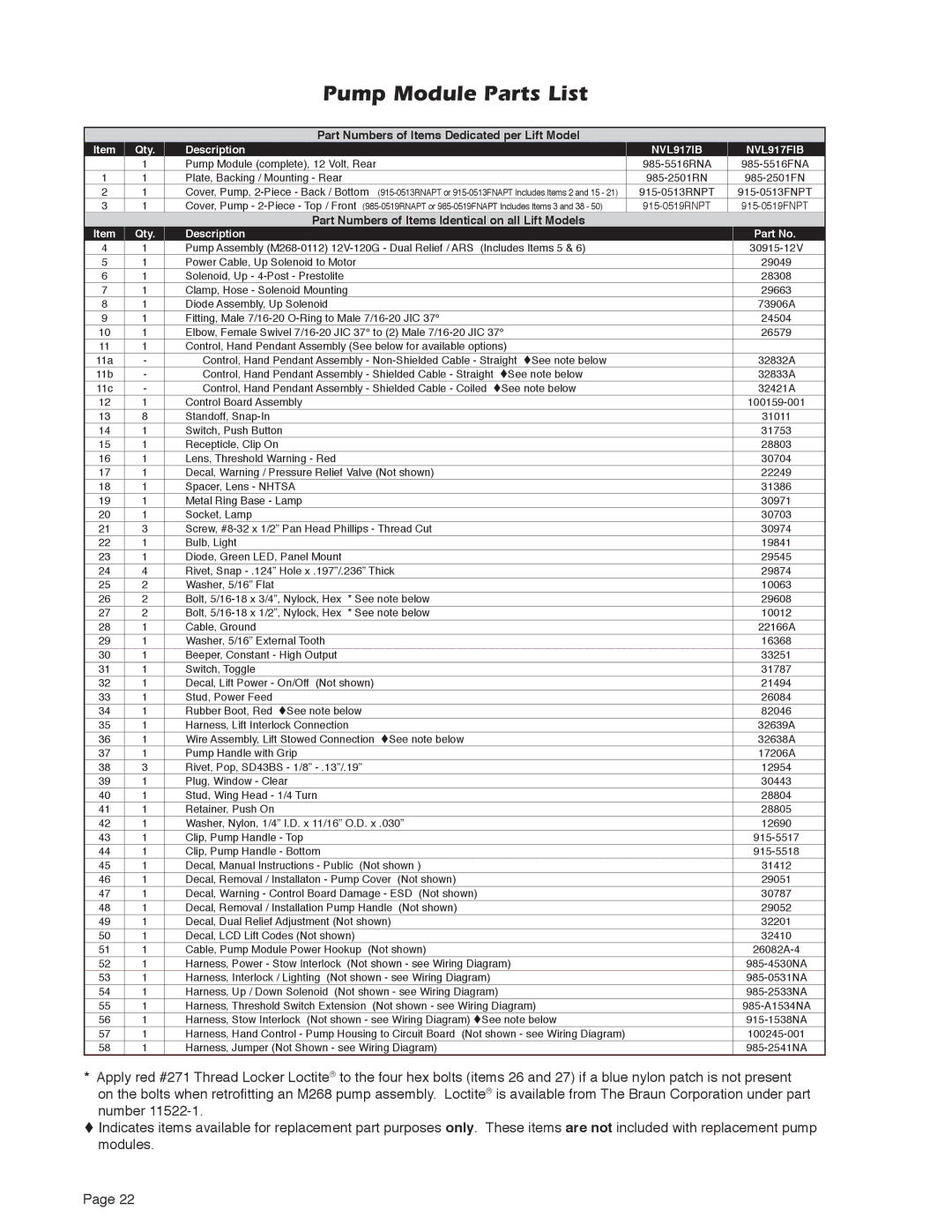
Pump Module Parts List
Part Numbers of Items Dedicated per Lift Model
Item | Qty. | Description | NVL917IB | NVL917FIB |
| 1 | Pump Module (complete), 12 Volt, Rear | ||
1 | 1 | Plate, Backing / Mounting - Rear | ||
2 | 1 | Cover, Pump, |
|
|
3 | 1 | Cover, Pump - |
Part Numbers of Items Identical on all Lift Models
Item | Qty. | Description |
| Part No. |
4 | 1 | Pump Assembly | ||
5 | 1 | Power Cable, Up Solenoid to Motor | 29049 | |
6 | 1 | Solenoid, Up - |
| 28308 |
7 | 1 | Clamp, Hose - Solenoid Mounting | 29663 | |
8 | 1 | Diode Assembly, Up Solenoid |
| 73906A |
9 | 1 | Fitting, Male | 24504 | |
10 | 1 | Elbow, Female Swivel | 26579 | |
11 | 1 | Control, Hand Pendant Assembly (See below for available options) |
| |
11a | - | Control, Hand Pendant Assembly - | 32832A | |
11b | - | Control, Hand Pendant Assembly - Shielded Cable - Straight tSee note below | 32833A | |
11c | - | Control, Hand Pendant Assembly - Shielded Cable - Coiled tSee note below | 32421A | |
12 | 1 | Control Board Assembly |
| |
13 | 8 | Standoff, |
| 31011 |
14 | 1 | Switch, Push Button |
| 31753 |
15 | 1 | Recepticle, Clip On |
| 28803 |
16 | 1 | Lens, Threshold Warning - Red |
| 30704 |
17 | 1 | Decal, Warning / Pressure Relief Valve (Not shown) | 22249 | |
18 | 1 | Spacer, Lens - NHTSA |
| 31386 |
19 | 1 | Metal Ring Base - Lamp |
| 30971 |
20 | 1 | Socket, Lamp |
| 30703 |
21 | 3 | Screw, | 30974 | |
22 | 1 | Bulb, Light |
| 19841 |
23 | 1 | Diode, Green LED, Panel Mount |
| 29545 |
24 | 4 | Rivet, Snap | 29874 | |
25 | 2 | Washer, 5/16” Flat |
| 10063 |
26 | 2 | Bolt, | * See note below | 29608 |
27 | 2 | Bolt, | * See note below | 10012 |
28 | 1 | Cable, Ground |
| 22166A |
29 | 1 | Washer, 5/16” External Tooth |
| 16368 |
30 | 1 | Beeper, Constant - High Output |
| 33251 |
31 | 1 | Switch, Toggle |
| 31787 |
32 | 1 | Decal, Lift Power - On/Off (Not shown) | 21494 | |
33 | 1 | Stud, Power Feed |
| 26084 |
34 | 1 | Rubber Boot, Red tSee note below | 82046 | |
35 | 1 | Harness, Lift Interlock Connection | 32639A | |
36 | 1 | Wire Assembly, Lift Stowed Connection tSee note below | 32638A | |
37 | 1 | Pump Handle with Grip |
| 17206A |
38 | 3 | Rivet, Pop, SD43BS - 1/8” | 12954 | |
39 | 1 | Plug, Window - Clear |
| 30443 |
40 | 1 | Stud, Wing Head - 1/4 Turn |
| 28804 |
41 | 1 | Retainer, Push On |
| 28805 |
42 | 1 | Washer, Nylon, 1/4” I.D. x 11/16” O.D. x .030” | 12690 | |
43 | 1 | Clip, Pump Handle - Top |
| |
44 | 1 | Clip, Pump Handle - Bottom |
| |
45 | 1 | Decal, Manual Instructions - Public (Not shown ) | 31412 | |
46 | 1 | Decal, Removal / Installaton - Pump Cover (Not shown) | 29051 | |
47 | 1 | Decal, Warning - Control Board Damage - ESD (Not shown) | 30787 | |
48 | 1 | Decal, Removal / Installation Pump Handle (Not shown) | 29052 | |
49 | 1 | Decal, Dual Relief Adjustment (Not shown) | 32201 | |
50 | 1 | Decal, LCD Lift Codes (Not shown) | 32410 | |
51 | 1 | Cable, Pump Module Power Hookup (Not shown) | ||
52 | 1 | Harness, Power - Stow Interlock (Not shown - see Wiring Diagram) | ||
53 | 1 | Harness, Interlock / Lighting (Not shown - see Wiring Diagram) | ||
54 | 1 | Harness, Up / Down Solenoid (Not shown - see Wiring Diagram) | ||
55 | 1 | Harness, Threshold Switch Extension (Not shown - see Wiring Diagram) | ||
56 | 1 | Harness, Stow Interlock (Not shown - see Wiring Diagram) tSee note below | ||
57 | 1 | Harness, Hand Control - Pump Housing to Circuit Board (Not shown - see Wiring Diagram) | ||
58 | 1 | Harness, Jumper (Not Shown - see Wiring Diagram) | ||
*Apply red #271 Thread Locker Loctite® to the four hex bolts (items 26 and 27) if a blue nylon patch is not present
on the bolts when retrofitting an M268 pump assembly. Loctite® is available from The Braun Corporation under part number
tIndicates items available for replacement part purposes only. These items are not included with replacement pump modules.
Page 22