Briggs & Stratton Power Products Automatic Transfer Switch
Installation and Operator’s Manual
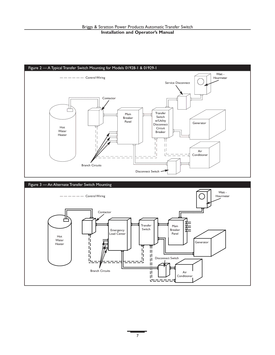
Figure 2 — A Typical Transfer Switch Mounting for Models |
| ||
— — — — — — Control Wiring |
|
| Watt - |
|
| Hourmeter | |
|
| Service Disconnect |
|
Contactor |
|
|
|
| Main | Transfer |
|
| Switch |
| |
| Breaker |
| |
| w/Utility |
| |
| Panel | Generator | |
| Disconnect | ||
|
| ||
Hot |
|
| |
| Circuit |
| |
Water |
| Breaker |
|
Heater |
|
|
|
|
|
| Air |
|
|
| Conditioner |
Branch Circuits |
|
|
|
|
| Disconnect Switch |
|
Figure 3 — An Alternate Transfer Switch Mounting
| Watt - |
— — — — — — Control Wiring | Hourmeter |
Contactor
| Transfer | Main |
Emergency | Switch | Breaker |
Load Center |
| Panel |
Hot
Water
Generator
Heater
| Disconnect Switch |
Branch Circuits | Air |
| |
| Conditioner |
7