Briggs & Stratton Power Products Automatic Transfer Switch
Installation and Operator’s Manual
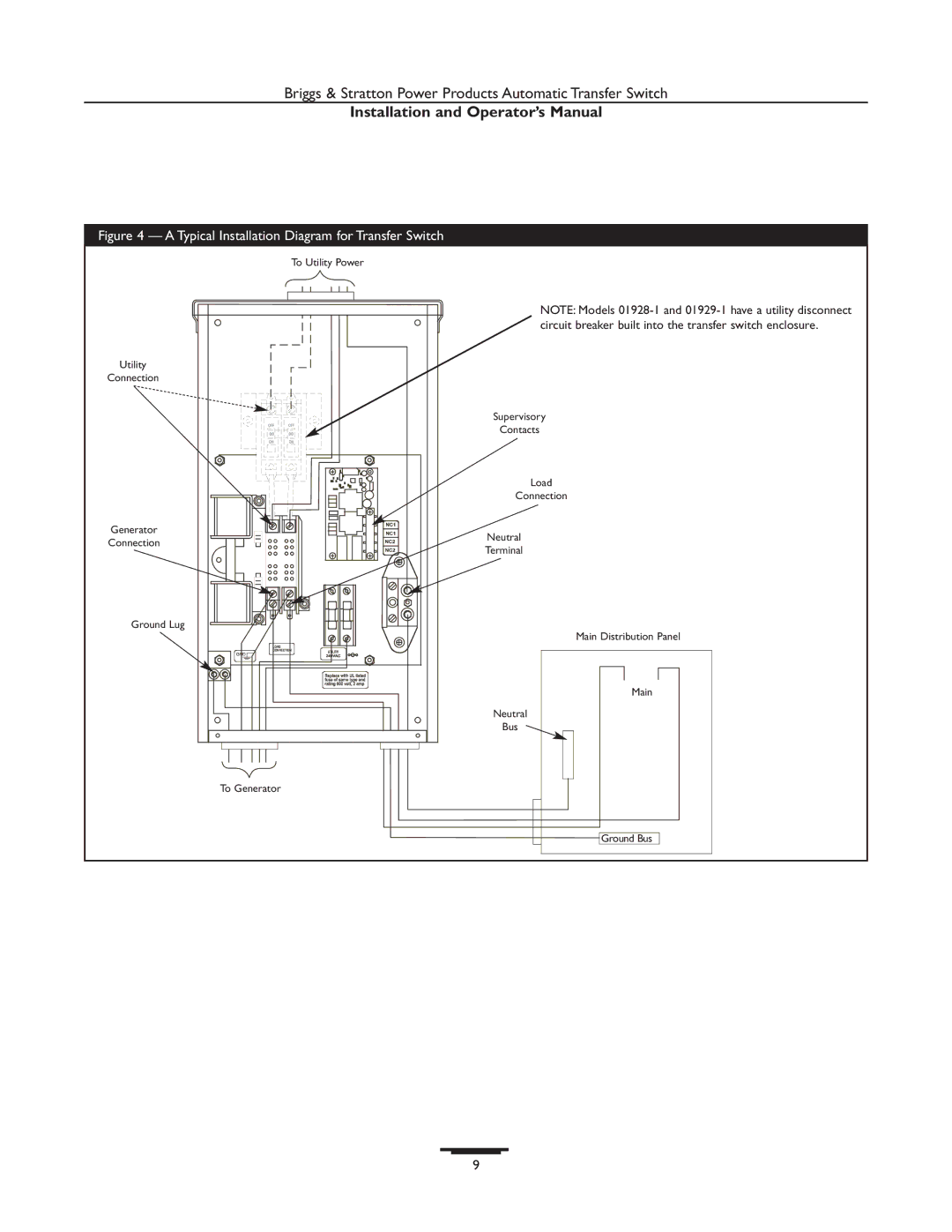
Figure 4 — A Typical Installation Diagram for Transfer Switch
To Utility Power
Utility
Connection
Generator
Connection
Ground Lug
NOTE: Models
Supervisory
Contacts
Load
Connection
Neutral
Terminal
Main Distribution Panel
![]()
![]() Main
Main![]()
![]()
![]()
Neutral
Bus
To Generator
![]() Ground Bus
Ground Bus
9