Briggs & Stratton Power Products Automatic Transfer Switch
Installation and Operator’s Manual
Power Wiring Interconnections
All wiring must be the proper size, properly supported and protected by conduit.
Complete the following connections between the transfer switch, main distribution panel, utility power and generator (Figure 4, on next page).
![]() WARNING
WARNING
Low voltage wire cannot be installed in same conduit as power voltage wiring.
•Failure to follow above warning could cause personal injury, damage and/or malfunction of equipment.
1.Ensure utility power is turned OFF. Connect utility power supply leads to transfer switch terminals marked “UTILITY CONNECTION”.
2.Connect utility neutral to the transfer switch “NEUTRAL” terminal.
3.Connect main distribution panel power leads to transfer switch terminals marked “LOAD CONNECTION”.
4.Connect main distribution panel neutral lead to transfer switch “NEUTRAL” terminal.
5.Connect generator power supply leads from the generator’s control panel to transfer switch terminals marked “GENERATOR CONNECTION”.
6.Connect generator Neutral from the control panel to the transfer switch “NEUTRAL” terminal.
7.Connect generator “GND” from the control panel to the transfer switch “GND” terminal.
8.Connect main distribution panel “GND” to the transfer switch “GND” terminal.
NOTE: Assure grounding electrode conductor is connected and bonded per applicable federal, state and local codes, standards and regulations.
9.Connect generator utility 240 VAC terminals to transfer switch utility 240 VAC terminals.
10.Tighten all wire connections/fasteners to proper torque. See inside transfer switch enclosure for proper torque values.
Supervisory Control Wiring
Terminal strip on control module in transfer switch has four connections for customer use.There are two sets of “Normally Closed” contacts available.They will be opened when generator power is required.These can be used to lock out large loads when powered by generator. Example: air conditioner, hot water heater, etc..
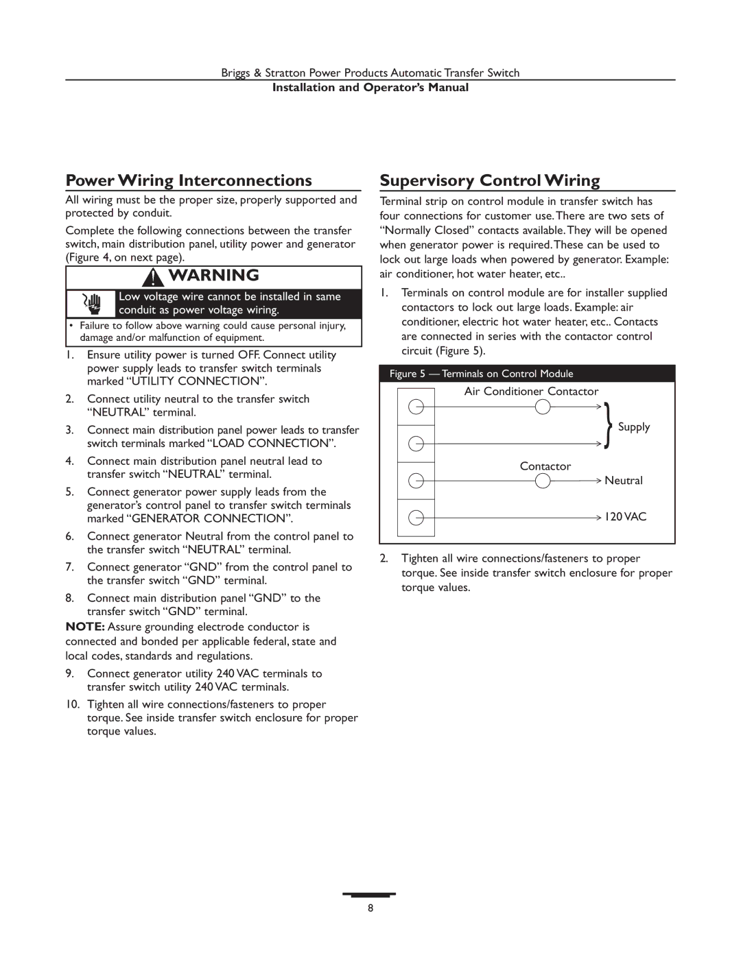
1.Terminals on control module are for installer supplied contactors to lock out large loads. Example: air conditioner, electric hot water heater, etc.. Contacts are connected in series with the contactor control circuit (Figure 5).
Figure 5 — Terminals on Control Module
Air Conditioner Contactor
Supply
Contactor
Neutral
120 VAC
2.Tighten all wire connections/fasteners to proper torque. See inside transfer switch enclosure for proper torque values.
8