Power Supply | Screws |
Power Supply
Optional External
Interface Cable
Molded Grommets | Drip Loop |
|
Internal Interface Cable
Drip Loop
TabDoor
Clip
4. Complete the Installation
Drip Loop
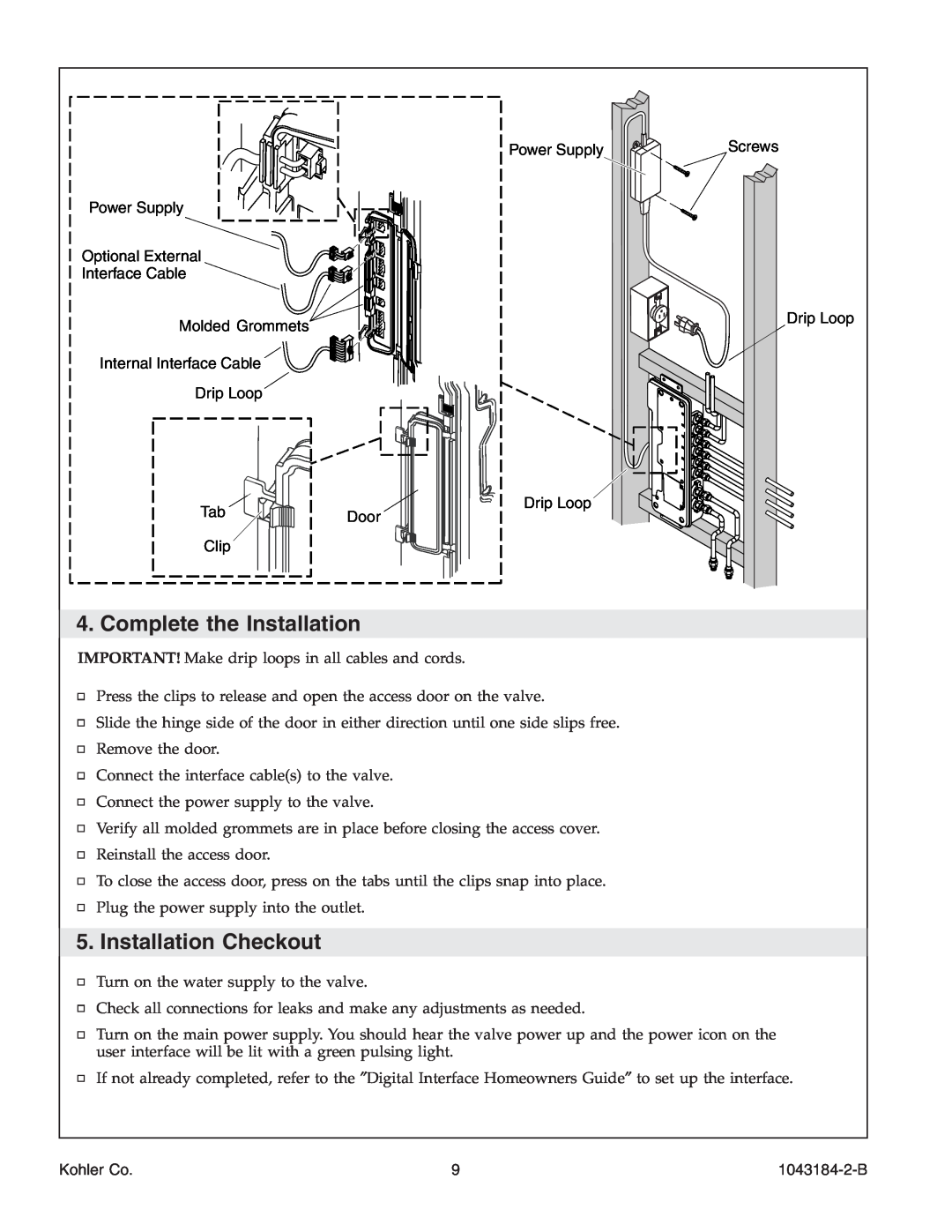
IMPORTANT! Make drip loops in all cables and cords.
Press the clips to release and open the access door on the valve.
Slide the hinge side of the door in either direction until one side slips free.
Remove the door.
Connect the interface cable(s) to the valve.
Connect the power supply to the valve.
Verify all molded grommets are in place before closing the access cover.
Reinstall the access door.
To close the access door, press on the tabs until the clips snap into place.
Plug the power supply into the outlet.
5. Installation Checkout
Turn on the water supply to the valve.
Check all connections for leaks and make any adjustments as needed.
Turn on the main power supply. You should hear the valve power up and the power icon on the user interface will be lit with a green pulsing light.
If not already completed, refer to the ″Digital Interface Homeowners Guide″ to set up the interface.
Kohler Co. | 9 |
