Briggs & Stratton Power Products Home Generator
Installation Manual
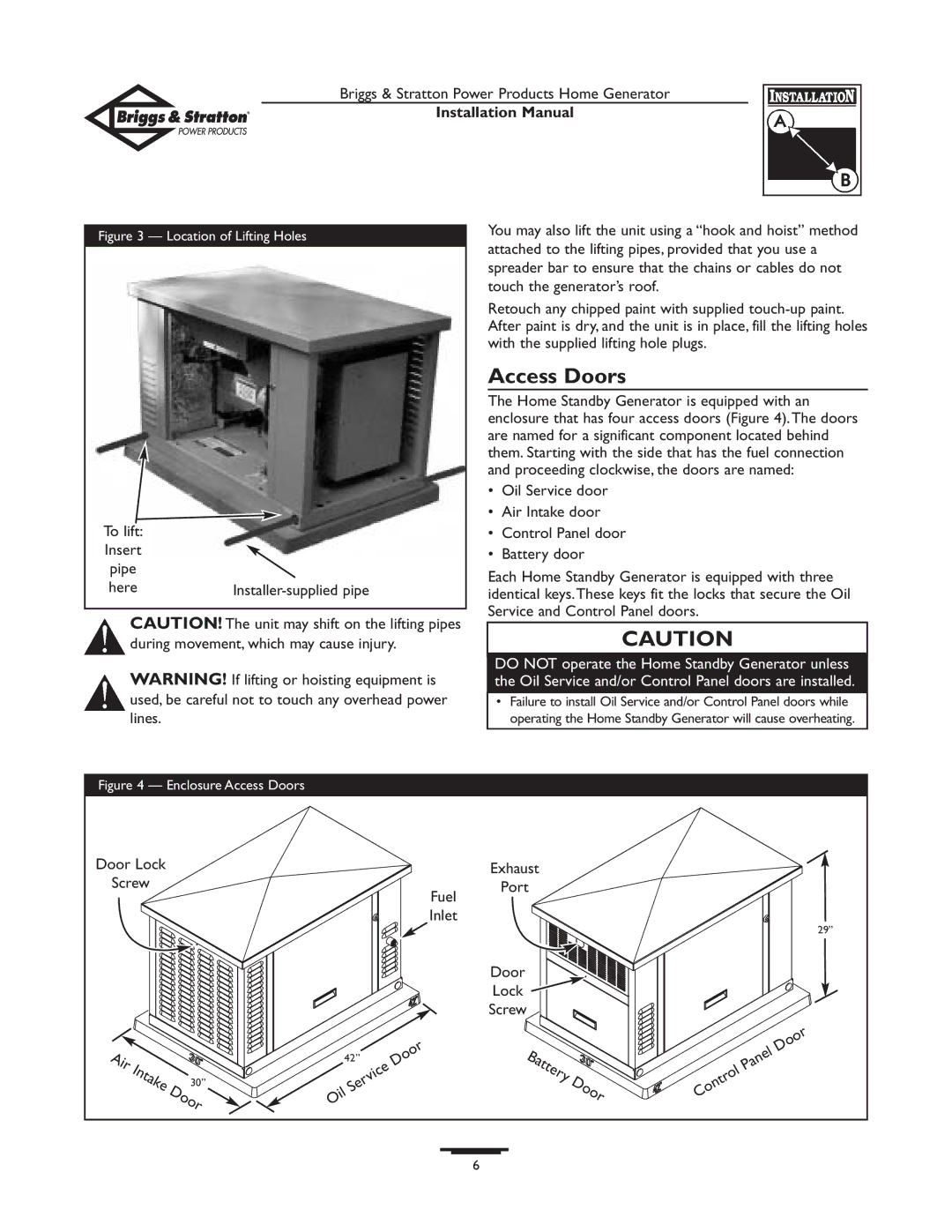
Figure 3 — Location of Lifting Holes
To lift: |
|
Insert |
|
pipe |
|
here |
![]() CAUTION! The unit may shift on the lifting pipes during movement, which may cause injury.
CAUTION! The unit may shift on the lifting pipes during movement, which may cause injury.
![]() WARNING! If lifting or hoisting equipment is used, be careful not to touch any overhead power lines.
WARNING! If lifting or hoisting equipment is used, be careful not to touch any overhead power lines.
You may also lift the unit using a “hook and hoist” method attached to the lifting pipes, provided that you use a spreader bar to ensure that the chains or cables do not touch the generator’s roof.
Retouch any chipped paint with supplied
Access Doors
The Home Standby Generator is equipped with an enclosure that has four access doors (Figure 4).The doors are named for a significant component located behind them. Starting with the side that has the fuel connection and proceeding clockwise, the doors are named:
•Oil Service door
•Air Intake door
•Control Panel door
•Battery door
Each Home Standby Generator is equipped with three identical keys.These keys fit the locks that secure the Oil Service and Control Panel doors.
CAUTION
DO NOT operate the Home Standby Generator unless the Oil Service and/or Control Panel doors are installed.
•Failure to install Oil Service and/or Control Panel doors while operating the Home Standby Generator will cause overheating.
Figure 4 — Enclosure Access Doors
Door Lock |
|
|
|
| Exhaust |
|
|
|
| |
Screw |
|
|
|
| Port |
|
|
|
| |
|
|
|
|
|
| Fuel |
|
|
|
|
|
|
|
|
|
| Inlet |
|
|
| 29” |
|
|
|
|
|
|
|
|
|
| |
|
|
|
|
|
| Door |
|
|
|
|
|
|
|
|
|
| Lock |
|
|
|
|
|
|
|
|
|
| Screw |
|
|
|
|
Air |
|
| 42” | Door | Battery |
|
| Panel | Door | |
Intake |
|
|
|
| ||||||
|
| Service | Door |
|
| |||||
| 30” |
|
| Control |
| |||||
|
|
|
|
| ||||||
|
|
|
|
|
| |||||
| Door |
|
|
|
|
| ||||
|
| Oil |
|
|
|
| ||||
|
|
|
|
|
|
| ||||
|
|
|
|
|
|
|
|
| ||
|
|
|
|
|
|
|
|
|
| |
|
|
|
|
|
| 6 |
|
|
|
|