JEFFERSON, WISCONSIN, U.S.A
BRIGGS & STRATTON POWER PRODUCTS GROUP, LLC
Operator’s Manual
Portable Generator
Engine
Where to Find Us
Generator
Model Number Revision Serial Number
Features and Controls
Table of Contents
Operator Safety
Assembly
Equipment Description
Operator Safety
Safety Rules
Hazard Symbols and Meanings
WHEN OPERATING EQUIPMENT
The engine exhaust from this product contains
WHEN ADDING OR DRAINING FUEL
WHEN STARTING EQUIPMENT
Excessively low speeds impose a heavy load
WHEN TESTING FOR ENGINE SPARK
Contact with muffler area can result in serious burns
Unintentional sparking can result in fire or electric shock
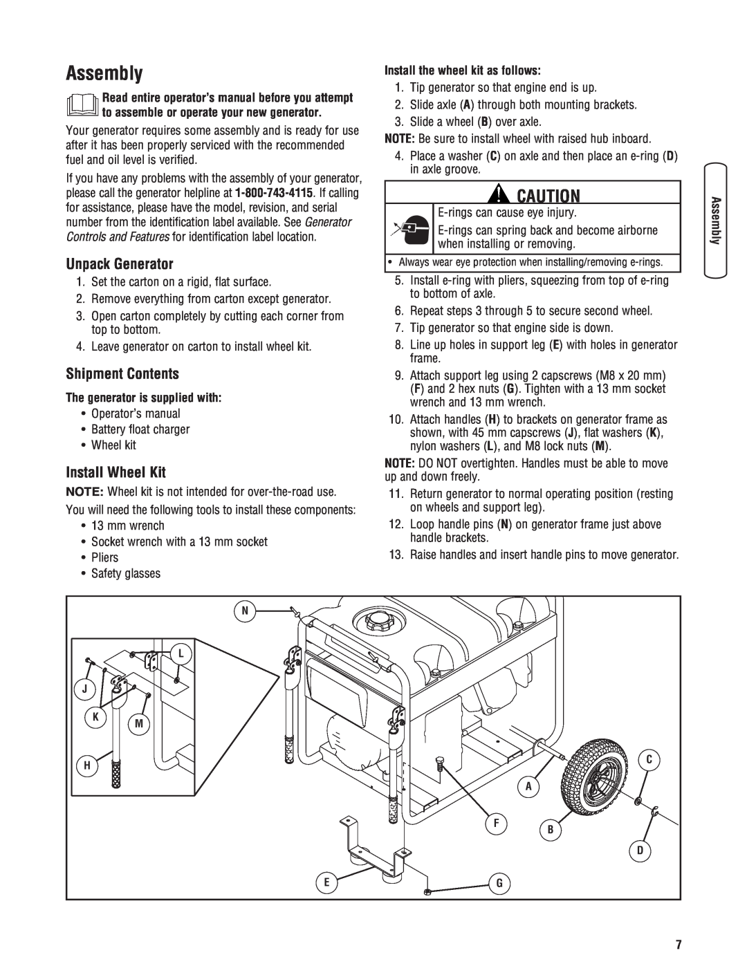
Install the wheel kit as follows
Assembly
Shipment Contents
Install Wheel Kit
Add Fuel
Attach Negative Battery Cable
To install
Verify Engine Oil Level
Special Requirements
Connecting to a Building’s Electrical System
System Ground
Generator Location
F - Recoil Starter - Used to start the engine
Features and Controls
B - Start Switch - Push to start the engine
C - Fuel Tank - Capacity of seven 7 U.S. gallons
NEMA L14-30
Battery Charger
IMPORTANT See Battery Maintenance for additional information
Cord Sets and Receptacles
Starting the Engine
Operation
Stopping the Engine
Connecting Electrical Loads
Cold Weather Operation
Building a Cold Weather Shelter
Creating a Temporary Cold Weather Shelter
Example
Power Management
Don’t Overload Generator
Capacity
Cleaning
Maintenance
Maintenance Schedule
Generator Maintenance
Adding Engine Oil
Engine Maintenance
Oil Oil Recommendations
Checking Oil Level
Service Spark Arrester
Service Air Cleaner
To service the air cleaner, follow these steps
Service Spark Plug
Check Valve Clearance
Clean Cooling System
Carburetor Adjustment
Clean and inspect the spark arrester as follows
Change Engine Oil
Storage
Generator Storage
Long Term Storage Instructions
Cause
Troubleshooting
Problem
Engine lacks power
Briggs & Stratton Emissions Control Defects Warranty Provisions
Emissions Control System Warranty
Briggs & Stratton Emissions Control Defects Warranty Coverage
Owner’s Warranty Responsibilities
Emission Information
BRIGGS & STRATTON POWER PRODUCTS GROUP, LLC JEFFERSON, WI, USA
LIMITED WARRANTY
WARRANTY PERIOD
ABOUT YOUR WARRANTY
Reserved
Common Service Parts
Product Specifications
Portable Generator
JEFFERSON, WISCONSIN, U.S.A
Manual del Operario
Generador portátil
BRIGGS & STRATTON POWER PRODUCTS GROUP, LLC
Motor
Dónde encontrarnos
Generador
Número de Modelo Revisión Número de Serie
Controles y características
Tabla de Contenido
Seguridad de operario
Montaje
Descripción del equipo
Seguridad de operario
AVISO
ADVERTENCIA
ADVERTENCIA
ADVERTENCIA
ADVERTENCIA
ADVERTENCIA
ADVERTENCIA
PRECAUCIÓN
ADVERTENCIA
ADVERTENCIA
El generador se entrega con
Montaje
Desembalaje del generador
Instale el juego de ruedas
AVISO
Conecte el cable negativo de la batería
Comprobar el nivel de aceite del motor
Para instalar
AVISO
Agregue combustible
El combustible debe reunir los siguientes requisitos
Gran altitud
Requisitos Especiales
Tierra del sistema
Conexión al sistema eléctrico de un edificio
Ubicación del generador
D - Tapa del Depósito del Aceite - Llene el motor con aceite aquí
Controles y características
F - Culatazo el Principio - Usó para comenzar motor
Tomas eléctricas dobles de 120 V CA y 20 A
Juegos de cordones y enchufes conectores
Cargador de batería
Dispositivo de seguridad de 120/240 V, 30 A
ADVERTENCIA
Operando
Encienda el motor
ADVERTENCIA
IMPORTANTE
Conexión de cargas eléctricas
Parada del motor
Operación durante un clima frío
ADVERTENCIA
Construcción de una estructura de protección para climas fríos
ADVERTENCIA
Control de la energía
No sobrecargar el generador
Capacidad
Ejemplo
Primeras Ocho 8 Horas
Mantenimiento
Plan de mantenimiento
Mantenimiento del generador
Adición de aceite del motor
Mantenimiento del motor
Aceite Recomendaciones sobre el aceite
Comprobación del nivel de aceite
Servicio del bujía
Servicio del depurador de aire
limpia B
Quite filtro de espuma C y papel el filtro D
Ajuste del carburador
Limpie e inspeccione el apagachispas de la siguiente manera
Sistema de refrigeración de aire
Comprobación de holgura de la válvula
Cambio de aceite
Almacenamiento
Generador
Almacenamiento para periodos prolongados
Accion
Resolución de problemas
Problemo
Causa
Garantía del sistema de control de emisiones
Garantías
Responsabilidades de la garantía del propietario
Información sobre emisiones
GARANTÍA LIMITADA
BRIGGS & STRATTON POWER PRODUCTS GROUP, LLC
BRIGGS & STRATTON POWER PRODUCTS GROUP, LLC JEFFERSON, WI, EE.UU
POLÍTICA DE GARANTÍA PARA EL PROPIETARIO DE GENERADOR PORTÁTIL
Especificaciones del producto
Generador portátil
Servicio común despide