INSTALLATION
4.As shown in Figure 7, cut, strip, and connect each wire to the appropriate terminal on the locking receptacle on the inlet box inner panel. Use the schematic affixed to the inside of the inlet box to make proper wire connections. When all connections have been made, reinstall the inlet box inner panel.
Figure 7 — Inlet Box Connections
Connecting Cord Set
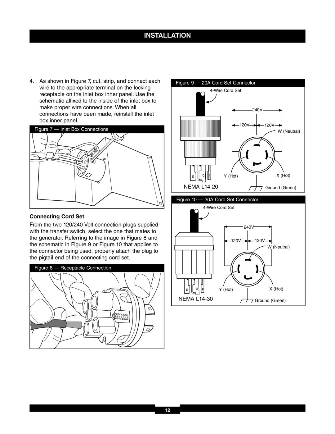
From the two 120/240 Volt connection plugs supplied with the transfer switch, select the one that mates to the generator. Referring to the image in Figure 8 and the schematic in Figure 9 or Figure 10 that applies to the connector being used, properly attach the plug to the pigtail end of the connecting cord set.
Figure 8 — Receptacle Connection
Figure 9 — 20A Cord Set Connector
240V
120V ![]() 120V
120V
W (Neutral)
Y (Hot) | X (Hot) |
NEMA | Ground (Green) |
Figure 10 — 30A Cord Set Connector
240V
120V ![]() 120V
120V
W (Neutral)
Y (Hot) | X (Hot) |
NEMA | Ground (Green) |
12