OPERATION
SYSTEM OPERATION
Load Management
The number of circuits that can be operated simultaneously during a utility failure will depend on the wattage capacity of your generator. Most optional standby system generators do not have the capacity to handle loads on all transfer switch circuits at the same time.
Review the load management plan developed with the installer. It may be necessary to selectively turn on and off certain loads while using generator power so that necessary appliances can be operated.
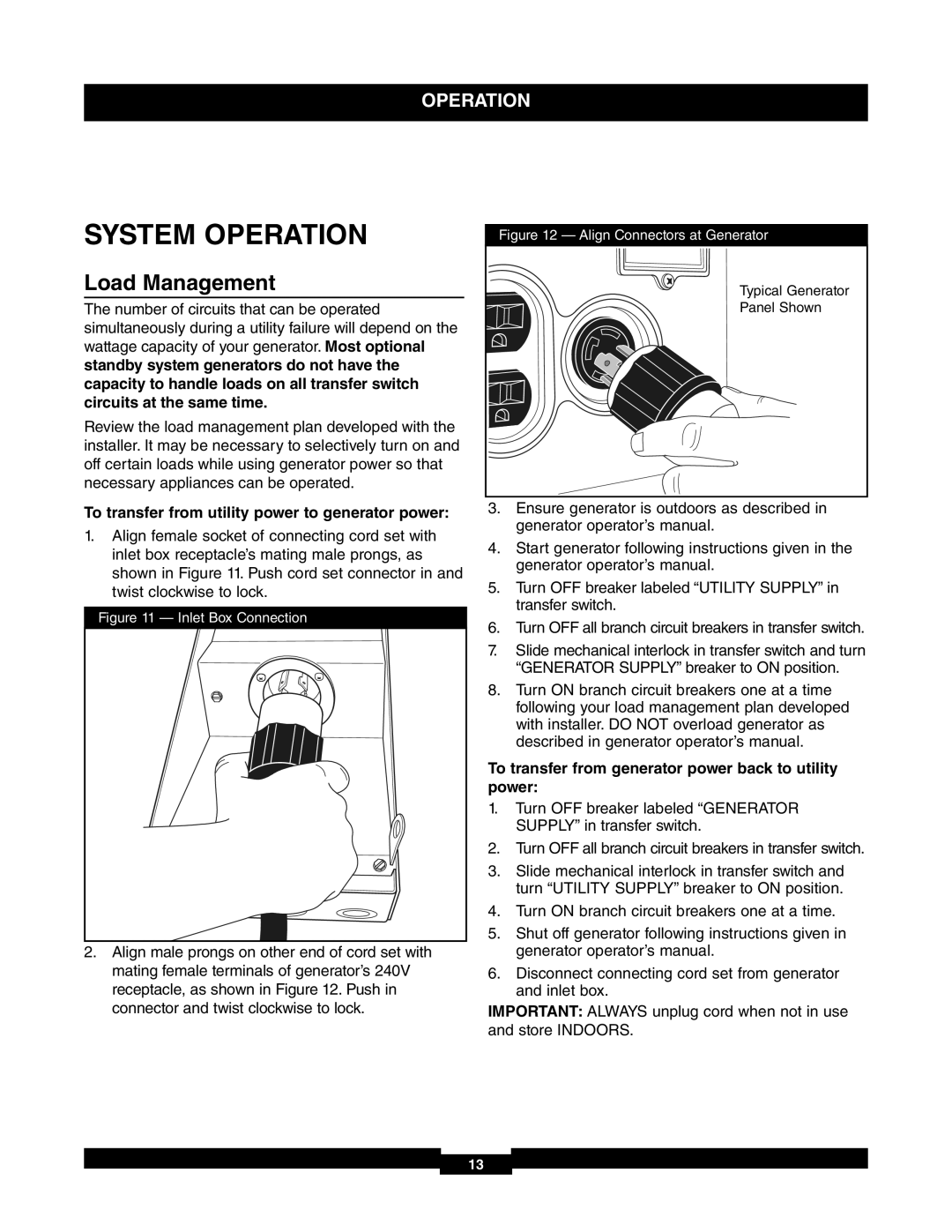
Figure 12 — Align Connectors at Generator
Typical Generator |
Panel Shown |
To transfer from utility power to generator power:
1.Align female socket of connecting cord set with inlet box receptacle’s mating male prongs, as shown in Figure 11. Push cord set connector in and twist clockwise to lock.
Figure 11 — Inlet Box Connection
2.Align male prongs on other end of cord set with mating female terminals of generator’s 240V receptacle, as shown in Figure 12. Push in connector and twist clockwise to lock.
3.Ensure generator is outdoors as described in generator operator’s manual.
4.Start generator following instructions given in the generator operator’s manual.
5.Turn OFF breaker labeled “UTILITY SUPPLY” in transfer switch.
6.Turn OFF all branch circuit breakers in transfer switch.
7.Slide mechanical interlock in transfer switch and turn “GENERATOR SUPPLY” breaker to ON position.
8.Turn ON branch circuit breakers one at a time following your load management plan developed with installer. DO NOT overload generator as described in generator operator’s manual.
To transfer from generator power back to utility power:
1.Turn OFF breaker labeled “GENERATOR SUPPLY” in transfer switch.
2.Turn OFF all branch circuit breakers in transfer switch.
3.Slide mechanical interlock in transfer switch and turn “UTILITY SUPPLY” breaker to ON position.
4.Turn ON branch circuit breakers one at a time.
5.Shut off generator following instructions given in generator operator’s manual.
6.Disconnect connecting cord set from generator and inlet box.
IMPORTANT: ALWAYS unplug cord when not in use and store INDOORS.
13