ASSEMBLY INSTRUCTIONS
![]() READ ALL SAFETY WARNINGS & ASSEMBLY INSTRUCTIONS CAREFULLY BEFORE ASSEMBLING OR OPERATING YOUR COOKER.
READ ALL SAFETY WARNINGS & ASSEMBLY INSTRUCTIONS CAREFULLY BEFORE ASSEMBLING OR OPERATING YOUR COOKER.
Inspect contents of the box to ensure all parts are included and undamaged.
FOR MISSING PARTS, PLEASE CALL CUSTOMER SERVICE AT 1-800-527-0717.
(Proof of purchase will be required.)
Tools required to assemble your cooker:
2 Adjustable wrenches
OR
Adjustable wrench and the following wrenches:
•d" Open end wrench
•w" Open end wrench
•f" Open end wrench
PARTS LIST:
1 Owner’s Manual
1 Cooker Stand
1 Burner Assembly
1 Hose & Regulator with Safety Tag
POL | Female | |
SAE | ||
Fitting | ||
Fitting | ||
| ||
Air Hole | Rotating | |
| ||
| Air Shutter |
NOTE: Make sure the male SAE fitting on the cooker is screwed into the air shutter and tightened securely. Do not
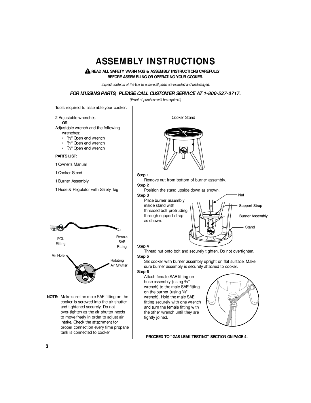
Cooker Stand
Step 1
Remove nut from bottom of burner assembly.
Step 2
Position the stand upside down as shown.
Step 3
Place burner assembly
inside stand with threaded bolt protruding
through support strap as shown.
Step 4
Thread nut onto bolt and securely tighten. Do not overtighten.
Step 5
Set cooker with burner assembly upright on flat surface. Make sure burner assembly is securely attached to cooker.
Step 6
Attach female SAE fitting on hose assembly (using w" wrench) to the male SAE fitting on the burner (using d" wrench). Hold the male SAE fitting securely with one wrench and turn the female fitting with the other wrench until they are tightly joined.
PROCEED TO “GAS LEAK TESTING” SECTION ON PAGE 4.
3