D2677, D2722, W1669, W1670 specifications
Woodstock W1670, W1669, D2722, and D2677 are exemplary woodworking machines that reflect the brand's commitment to quality and efficiency in wood processing. Each of these models brings distinct features, technologies, and characteristics designed to enhance productivity and user experience in woodworking applications.The Woodstock W1670 is a powerful table saw that stands out for its robust construction and innovative features. It features a high-performance motor that ensures precision cuts in various wood types, making it suitable for both professional and amateur woodworkers. The saw is equipped with an adjustable blade height and angle, allowing users to achieve the desired cut with ease. Additionally, its large tabletop provides ample workspace, promoting stability and maneuverability during operations.
The Woodstock W1669 is a versatile bandsaw that excels in creating intricate cuts and curves. This model is designed with a reliable motor that delivers consistent power, facilitating effective cutting through dense materials. One of its notable characteristics is the spacious throat capacity, allowing users to work with larger workpieces. The precision-engineered blade guides reduce friction, promoting longer blade life and higher quality cuts. Furthermore, the easy-to-read tension indicator ensures optimal blade tension for enhanced performance.
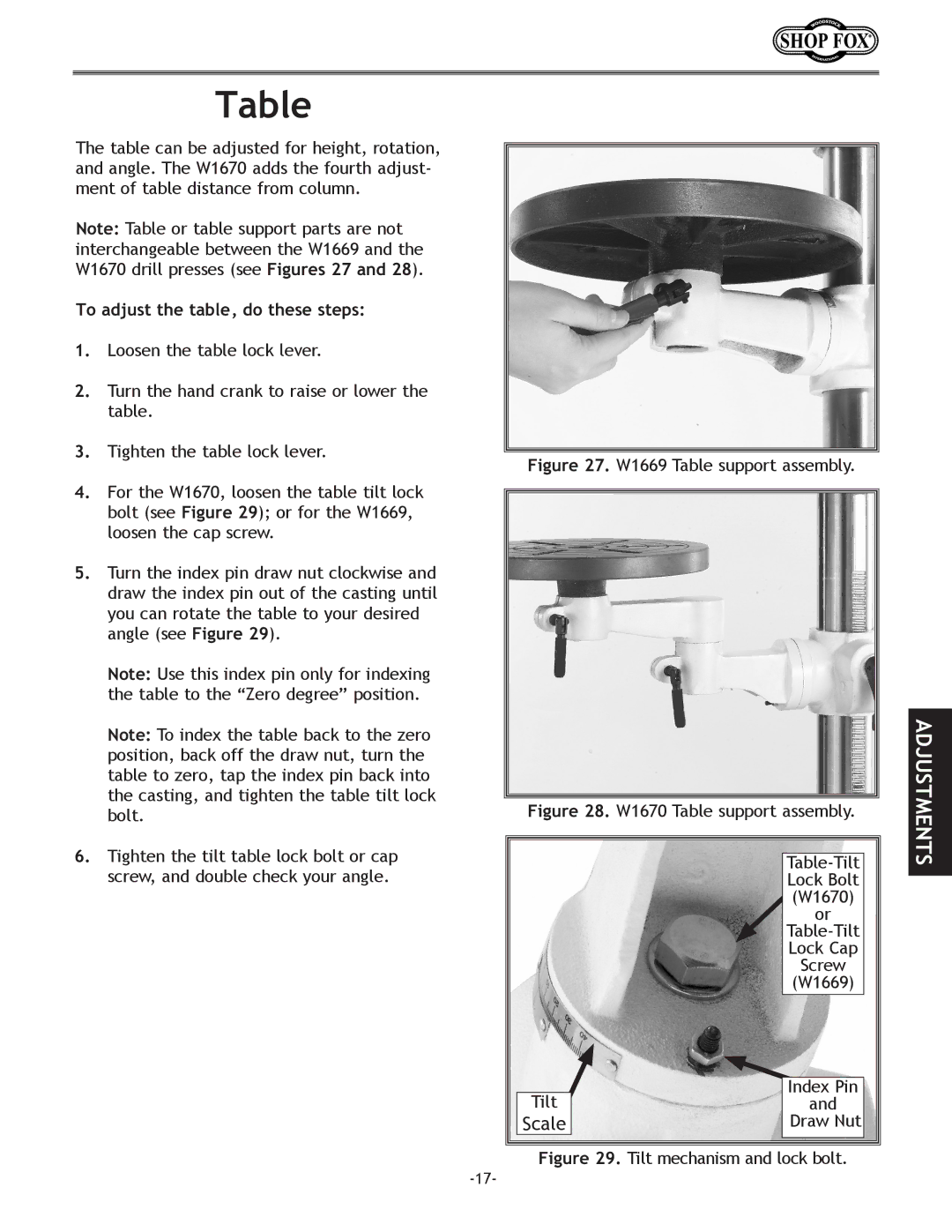
Moving to the D2722, this drill press is engineered for precision drilling tasks. It features digital readouts for depth control, ensuring accuracy in repetitive tasks. The heavy-duty construction contributes to reduced vibrations, which is essential for achieving clean holes in various materials. This model also supports variable speed settings, allowing users to tailor the drilling speed for different applications and materials. The adjustable work table adds to the convenience, making it easier to accommodate various workpiece sizes.
Lastly, the D2677 is a rugged planer designed for smoothing and finishing surfaces. It boasts a powerful motor that enables smooth operation through hard and soft woods alike. The adjustable depth of cut feature allows for precise thickness adjustments, ensuring uniformity in finished pieces. Additionally, the infeed and outfeed tables are designed to support larger stock, improving workflow efficiency. The dust collection port is another beneficial feature, facilitating a cleaner workspace.
In conclusion, the Woodstock W1670, W1669, D2722, and D2677 models excel in their respective functions, showcasing advanced technologies and user-friendly designs, ultimately making them essential tools for any woodworking shop. Whether cutting, drilling, or finishing, these machines ensure high-quality results and enhanced productivity.

