Sending a Message to a Destination Controller (Nodes 0 to 49)
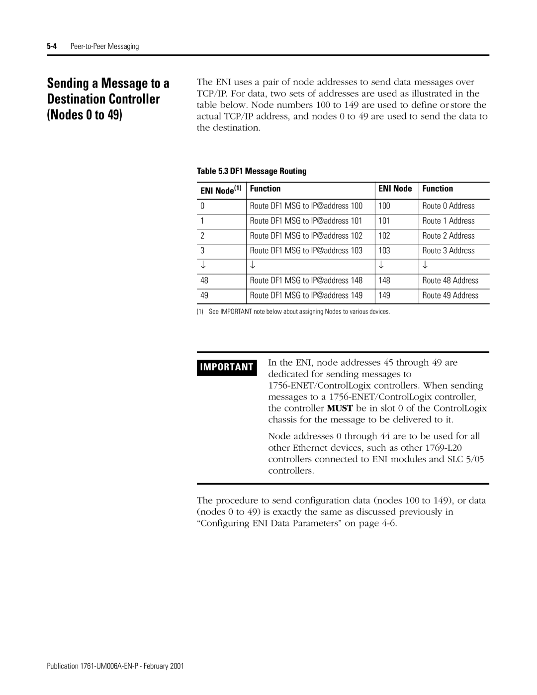
The ENI uses a pair of node addresses to send data messages over TCP/IP. For data, two sets of addresses are used as illustrated in the table below. Node numbers 100 to 149 are used to define or store the actual TCP/IP address, and nodes 0 to 49 are used to send the data to the destination.
Table 5.3 DF1 Message Routing
ENI Node(1) | Function | ENI Node | Function |
0 | Route DF1 MSG to IP@address 100 | 100 | Route 0 Address |
|
|
|
|
1 | Route DF1 MSG to IP@address 101 | 101 | Route 1 Address |
|
|
|
|
2 | Route DF1 MSG to IP@address 102 | 102 | Route 2 Address |
|
|
|
|
3 | Route DF1 MSG to IP@address 103 | 103 | Route 3 Address |
|
|
|
|
↓ | ↓ | ↓ | ↓ |
|
|
|
|
48 | Route DF1 MSG to IP@address 148 | 148 | Route 48 Address |
|
|
|
|
49 | Route DF1 MSG to IP@address 149 | 149 | Route 49 Address |
|
|
|
|
(1) See IMPORTANT note below about assigning Nodes to various devices.
IMPORTANT
In the ENI, node addresses 45 through 49 are dedicated for sending messages to
Node addresses 0 through 44 are to be used for all other Ethernet devices, such as other
The procedure to send configuration data (nodes 100 to 149), or data (nodes 0 to 49) is exactly the same as discussed previously in “Configuring ENI Data Parameters” on page
Publication
