ENI Configuration (Node 248 to 254) | |
|
|
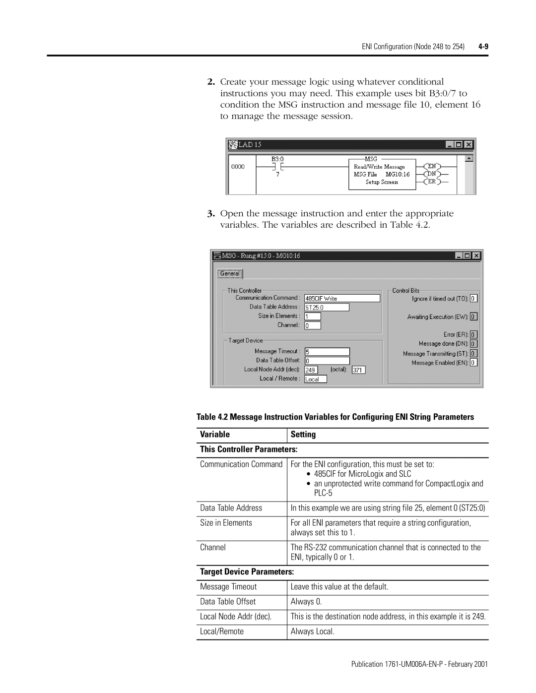
2.Create your message logic using whatever conditional instructions you may need. This example uses bit B3:0/7 to condition the MSG instruction and message file 10, element 16 to manage the message session.
3.Open the message instruction and enter the appropriate variables. The variables are described in Table 4.2.
Table 4.2 Message Instruction Variables for Configuring ENI String Parameters
Variable | Setting |
|
|
This Controller Parameters: | |
|
|
Communication Command | For the ENI configuration, this must be set to: |
| • 485CIF for MicroLogix and SLC |
| • an unprotected write command for CompactLogix and |
| |
|
|
Data Table Address | In this example we are using string file 25, element 0 (ST25:0) |
|
|
Size in Elements | For all ENI parameters that require a string configuration, |
| always set this to 1. |
|
|
Channel | The |
| ENI, typically 0 or 1. |
|
|
Target Device Parameters: | |
|
|
Message Timeout | Leave this value at the default. |
|
|
Data Table Offset | Always 0. |
|
|
Local Node Addr (dec). | This is the destination node address, in this example it is 249. |
|
|
Local/Remote | Always Local. |
|
|
Publication