Connecting | |
|
|
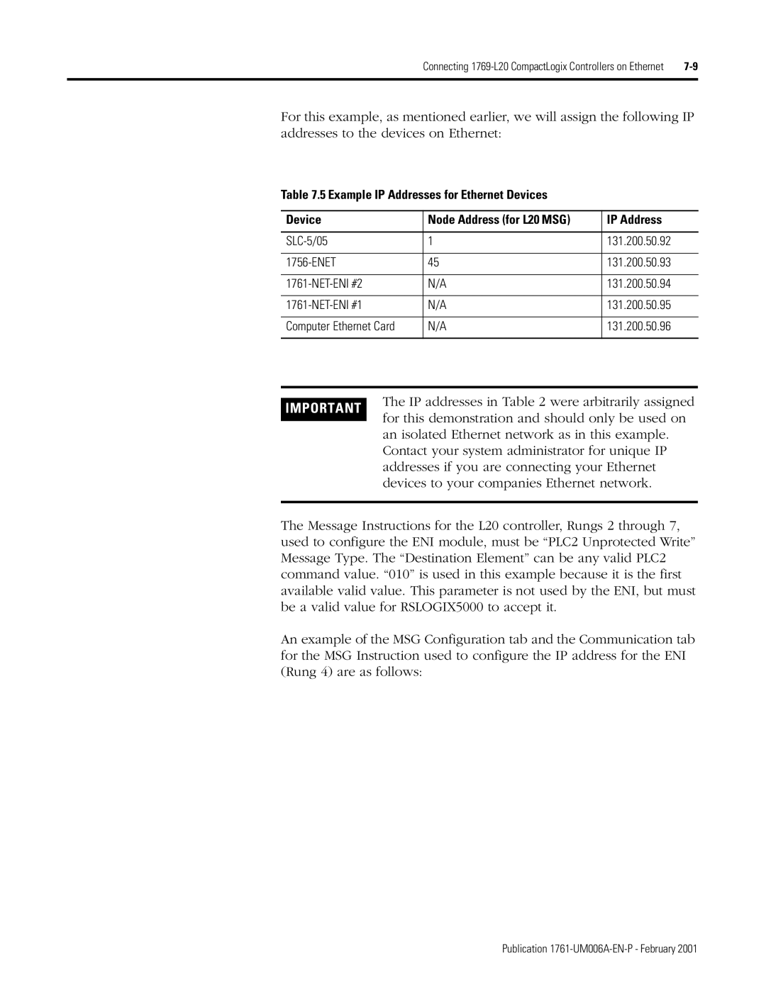
For this example, as mentioned earlier, we will assign the following IP addresses to the devices on Ethernet:
Table 7.5 Example IP Addresses for Ethernet Devices
Device | Node Address (for L20 MSG) | IP Address |
|
|
|
1 | 131.200.50.92 | |
|
|
|
45 | 131.200.50.93 | |
|
|
|
N/A | 131.200.50.94 | |
|
|
|
N/A | 131.200.50.95 | |
|
|
|
Computer Ethernet Card | N/A | 131.200.50.96 |
|
|
|
IMPORTANT
The IP addresses in Table 2 were arbitrarily assigned for this demonstration and should only be used on an isolated Ethernet network as in this example. Contact your system administrator for unique IP addresses if you are connecting your Ethernet devices to your companies Ethernet network.
The Message Instructions for the L20 controller, Rungs 2 through 7, used to configure the ENI module, must be “PLC2 Unprotected Write” Message Type. The “Destination Element” can be any valid PLC2 command value. “010” is used in this example because it is the first available valid value. This parameter is not used by the ENI, but must be a valid value for RSLOGIX5000 to accept it.
An example of the MSG Configuration tab and the Communication tab for the MSG Instruction used to configure the IP address for the ENI (Rung 4) are as follows:
