STEP 1:
a.Turn base pan upside down to assemble. Attach leg brackets to base pan with
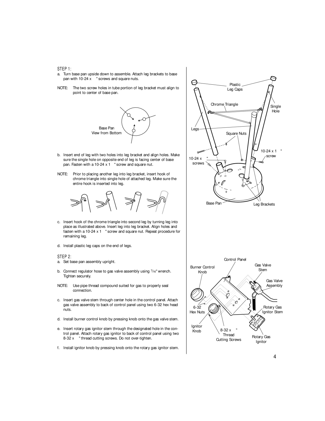
NOTE: The two screw holes in tube portion of leg bracket must align to point to center of base pan.
Base Pan
View from Bottom
Plastic
Leg Caps
Chrome Triangle | Single |
| Hole |
Legs
Square Nuts
10-24 x 12"
b.Insert end of leg with two holes into leg bracket and align holes. Make
sure the single hole on opposite end of leg is facing center of base pan. Fasten with a
NOTE: Prior to placing another leg into leg bracket, insert hook of chrome triangle into single hole of attached leg. Make sure the entire hook is inserted into leg.
![]()
screw
c.Insert hook of the chrome triangle into second leg by turning leg into
place as illustrated above. Insert leg into leg bracket. Align holes and fasten with a
d.Install plastic leg caps on the end of legs.
STEP 2:
a.Set base pan assembly upright.
b.Connect regulator hose to gas valve assembly using 7/16" wrench. Tighten securely.
NOTE: Use pipe thread compound suited for gas to properly seal connection.
c.Insert gas valve stem through center hole in the control panel. Attach gas valve assembly to back of control panel using two
d.Install burner control knob by pressing knob onto the gas valve stem.
e.Insert rotary gas ignitor stem through the designated hole in the con-
trol panel. Attach rotary gas ignitor to back of control panel using two
f.Install ignitor knob by pressing knob onto the rotary gas ignitor stem.
Base Pan | Leg Brackets |
| Control Panel | |
Burner Control | Gas Valve | |
Stem | ||
Knob | ||
|
Gas Valve
Assembly
Rotary Gas | |
Hex Nuts | Ignitor Stem |
Ignitor |
| |
Knob |
| |
| Thread | Rotary Gas |
| Cutting Screws | |
| Ignitor | |
|
|
4