STEP 3:
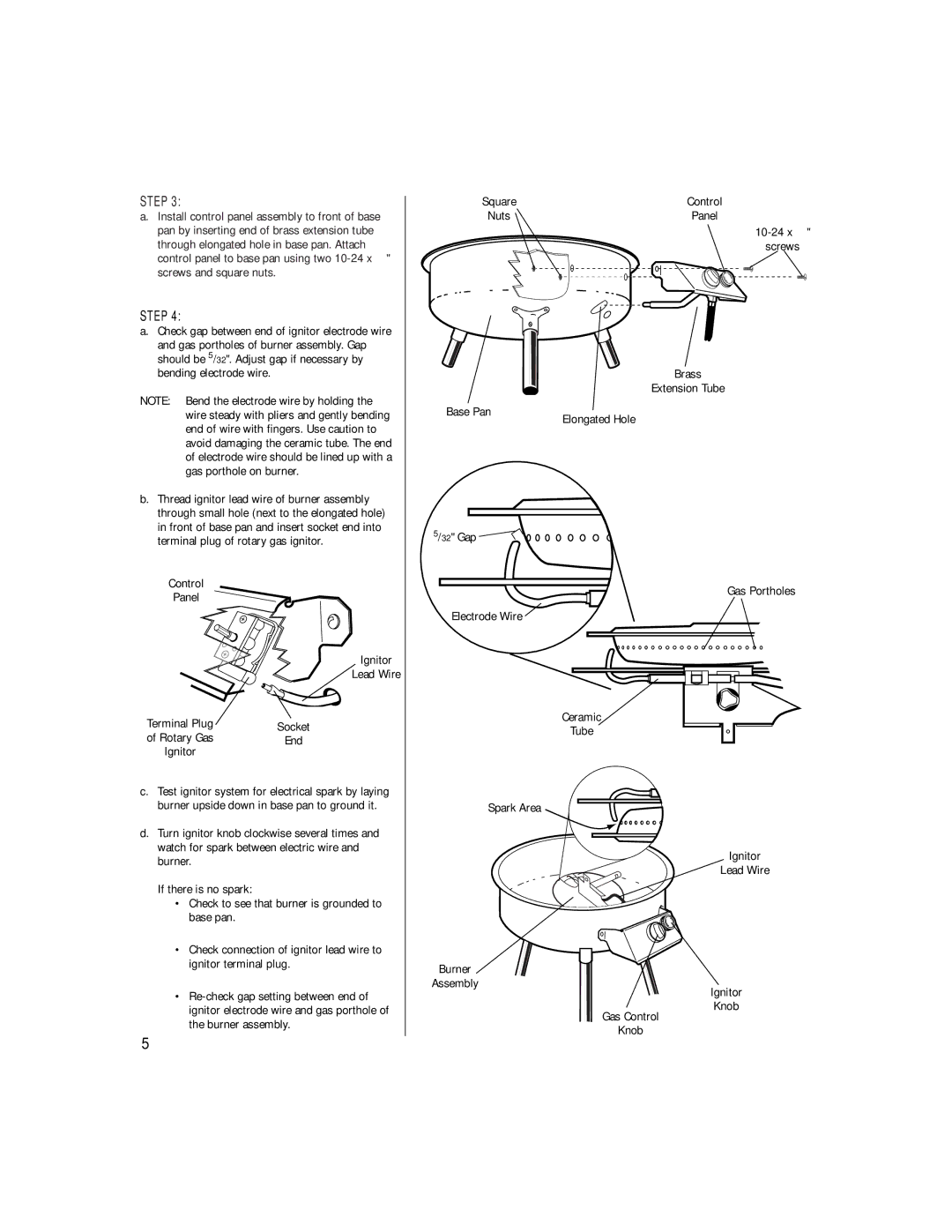
a. Install control panel assembly to front of base |
Square | Control |
Nuts | Panel |
pan by inserting end of brass extension tube |
through elongated hole in base pan. Attach |
control panel to base pan using two |
screws and square nuts. |
STEP 4:
a.Check gap between end of ignitor electrode wire
and gas portholes of burner assembly. Gap should be 5/32". Adjust gap if necessary by bending electrode wire.
NOTE: Bend the electrode wire by holding the wire steady with pliers and gently bending end of wire with fingers. Use caution to avoid damaging the ceramic tube. The end of electrode wire should be lined up with a gas porthole on burner.
b.Thread ignitor lead wire of burner assembly through small hole (next to the elongated hole) in front of base pan and insert socket end into terminal plug of rotary gas ignitor.
Control
Panel
Ignitor
Lead Wire
Terminal Plug | Socket |
of Rotary Gas | End |
Ignitor |
|
c.Test ignitor system for electrical spark by laying burner upside down in base pan to ground it.
d.Turn ignitor knob clockwise several times and watch for spark between electric wire and burner.
If there is no spark:
•Check to see that burner is grounded to base pan.
•Check connection of ignitor lead wire to ignitor terminal plug.
•
Base Pan
5/32" Gap ![]()
![]()
![]()
![]()
Electrode Wire
Spark Area
Burner
Assembly
screws
Brass
Extension Tube
Elongated Hole
Gas Portholes
Ceramic
Tube
Ignitor
Lead Wire
Ignitor
Knob
Gas Control
Knob
5
