TOOLS AND MATERIALS REQUIRED

†Drill, electric or ratchet drive

†1/8" Drill bit for drilling pilot holes

†1-1/4" wood bit for drilling electrical wiring access hole

†One straight blade and one phillips head screw- driver

†Pliers

†Pencil and ruler and/or tape measure

†Saber saw or keyhole saw for cutting 1" x 2" wood strips to length and cutting wall or cabinet openings

†Caulking, metal snips, duct tape, duct (with elbows and transition, if necessary) and roof or wall cap, as required

†Electrical wiring and supplies of type to comply with local codes

The following materials are required only for installa- tions on recessed bottom kitchen cabinets:

†Two 1" x 2" x 12" (approximate length) wood strips (purchase locally)

†Four 1-1/4" long flat head wood screws (purchase locally)

PLANNING DUCTWORK INSTALLATION

(This section for 40000 and 42000 hoods only. 41000 hoods skip this section and go on to “Prepare the Hood”.)

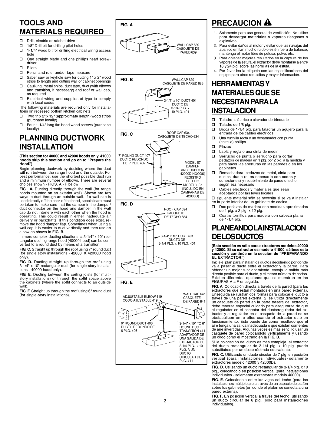
Begin planning ductwork by deciding where the duct will run between the range hood and the outside. For best performance, use the shortest possible duct run and a minimum number of elbows. There are several choices shown - FIGS. A - F below.

FIG. A. Ducting directly through the wall (for range hoods mounted on an exterior wall). Shown are two ways to duct through an outside wall. If a wall cap is used directly off the back of the hood, special care must be taken to make sure that the damper in the damper/ duct connector on the hood and damper in the wall cap do not interfere with each other when the hood is operating. This could result in either inadequate air delivery or backdrafts. If this condition does exist, re- move the hood damper flap. Sometimes when using a wall cap it is easier to duct vertically and then use an elbow as shown in FIG. B.

In more complex ducting situations, a 3-1/4" x 10" rec- tangular ducting range hood (40000 hood) can be con- verted to a round duct by means of a transition.

FIG. C. Straight up through the roof using 7" round duct (for single story installations - 42000 & 42000D hood only).

FIG. D. Ducting straight up through the roof using 3-1/4" x 10" rectangular duct (for single story installa- tions - 40000 hood only).

FIG. A

WALL CAP 639

CASQUETE DE

PARED 639

FIG. B

WALL CAP 639


CASQUETE DE PARED 639

3-1/4" X 10" DUCT 401

DUCTO DE

3-1/4 PLG. X

10 PLG. 401

FIG. C

ROOF CAP 634

CASQUETE DE TECHO 634


7" ROUND DUCT 407

DUCTO REDONDO

DE 7 PLG. 407MODEL 87 DAMPER

(INCLUDED ON

42000D HOODS)

REGISTRO

DE TIRO

MODELO 87

(INCLUIDO EN

CAMPANAS DE

42000D)

FIG. D

ROOF CAP 634

CASQUETE

DE TECHO 634

3-1/4" X 10" DUCT 401

DUCTO DE

3-1/4 PLG. X 10 PLG. 401

PRECAUCION !

1.Solamente para uso general de ventilación. No utilice para descargar materiales o vapores riesgosos o explosivos.

2.Para evitar daños al motor y evitar que las navajas del abanico emitan mucho ruido o estén fuera de balance, mantenga el motor libre de pelusa, polvo, etc.

3.Para obtener mejores resultados en la captura de los vapores de la estufa, el extractor debe montarse a entre 18 y 24 plg. sobre las hornillas de la estufa.

4.Por favor lea la etiqueta con las especificaciones del equipo para otros requisitos y mayor información.

HERRAMIENTASY

MATERIALES QUE SE

NECESITAN PARALA

INSTALACION

†Taladro, eléctrico o clavador de trinquete

†Taladro de 1/8 plg.

†Broca de 1-1/4 plg. para taladrar un agujero para la entrada de los cables eléctricos

†Una cuchilla recta y un desarmador con punta (estrella) phillips

†Pinzas

†Lapíz y regla o una cinta de medir

†Serrucho de punta o serrucho para cortar pedazos de madera en 1 plg. por 2 plg. a la medida y para hacer las aberturas en las paredes o en los gabinetes

†Remachadora, pedazos de metal, cinta para ductos, ducto (si es necesario con codos y conexiones) y recubrimiento de pared o techo, según sea necesario

†Cables eléctricos y materiales que sean aceptados por las leyes locales

El siguiente material sólo se necesita si se va a instalar en la parte inferior de un gabinete de cocina:

†Dos pedazos de madera con medidas aproximadas de 1 plg. x 2 plg. x 12 plg.

†Cuatro tornillos para madera con cabeza plana de 1-1/4 plg.

PLANEANDOLAINSTALACION DELOSDUCTOS

(Esta sección es sólo para extractores modelos 40000 y 42000. Si su extractor es modelo 41000, sáltese esta sección y continúe en la sección de “PREPARANDO EL EXTRACTOR”.)

Inicie el plan para instalar los ductos decidiendo por dónde va a pasar el ducto entre el extractor y la pared. Para obtener un mejor funcionamiento, escoja la salida más

FIG. E. Ducting between the ceiling joists (for multi- story installations) or through the soffit space above the cabinets (where the soffit connects to an outside wall).

FIG. F. Straight up through the roof using 6" round duct (for single-story installations).

FIG. E

ADJUSTABLE ELBOW 419 CODO AJUSTABLE 419

6" ROUND DUCT 406 DUCTO REDONDO DE 6 PLG. 406

WALL CAP 641 CASQUETE DE PARED 641

3-1/4" X 10" TO 6"

ROUND DUCT TRANSITION 411 ADAPTADOR DE UNA SALIDA DE EXTRACTOR DE 3-1/4 PLG. X 10 PLG. A UN DUCTO CIRCULAR DE 6 PLG. 411

directa posible para el ducto, y el menor número de codos. Existen diferentes opciones que se muestran en las FIGURAS A a F enseguida.

FIG. A. Colocación directa a través de la pared (para los extractores que están montados en una pared externa). Enseguida se ilustran dos formas para colocar el ducto a través de una pared externa. Si se utiliza directamente un casquete de pared en la parte trasera del extractor, debe tenerse especial cuidado para asegurarse de que el regulador en el conector del ducto/regulador del ex- tractor y el regulador en el casquete de la pared no se obstaculicen entre ellos cuando el extractor esté en funcionamiento. Esto puede dar como resultado que el aire tenga una salida inadecuada o que existan corrientes de aire invertidas. Algunas veces es más sencillo usar un casquete de pared colocándolo verticalmente y usando un codo como el mostrado en la FIG. B.

Si la colocación del ducto es más compleja, el extractor del ducto rectangular de 3-1/4 plg. x 10 plg. puede substituirse por un ducto rédondo equivalente.

FIG. C. Utilizando un ducto circular de 7 plg. en posición vertical (para instalaciones individuales - solamente extractores modelo 42000 y 42000D).

FIG. D. Utilizando un ducto rectangular de 3-1/4 plg. x 10 plg., colocándolo en posición vertical (para instalaciones individuales - solamente extractores modelo 40000).

FIG. E. Colocándolo entre las vigas del techo (para las instalaciones múltiples) o a través de un espacio de plafón sobre los gabinetes (en donde el plafón se conecta a una pared externa).

2

FIG. F. En posición vertical a través del techo, utilizando un ducto circular de 6 plg. (sólo para instalaciones individuales).

Page 2
Image 2
Broan 412404 Planning Ductwork Installation, Precaucion, Tools and Materials Required, Planeandolainstalacion Delosductos

412404 specifications

The Broan 412404 is an expertly engineered range hood that combines powerful ventilation with sleek design, making it a valuable addition to modern kitchens. This model is particularly favored for its efficient performance and aesthetic appeal.

One of the standout features of the Broan 412404 is its powerful 400 CFM blower, providing ample air circulation to effectively remove smoke, odors, and steam during cooking. This high-performance motor is designed to operate quietly, minimizing distraction while maintaining a peaceful kitchen environment. The two-speed settings allow users to customize ventilation power according to the type of cooking being done, whether it's a light sauté or a more intense frying session.

The range hood is crafted from durable stainless steel, which not only adds a contemporary finish to any kitchen but also ensures ease of cleaning and longevity. The sleek design fits seamlessly into various kitchen configurations, from traditional to modern.

Incorporating advanced technologies, the Broan 412404 features a single blower that maximizes airflow while maintaining energy efficiency. The integrated dishwasher-safe aluminum grease filters effectively trap grease and are easy to clean, promoting better hygiene in the kitchen.

Another highlight of the Broan 412404 is its recessed lighting, which provides enhanced visibility over the cooking surface. This not only improves functionality when preparing meals but also elevates the overall aesthetic of the kitchen. The energy-efficient bulbs used in the lighting will help reduce electricity consumption while providing adequate illumination.

Installation of the Broan 412404 is straightforward, making it a feasible option for both new kitchen builds and upgrades. The unit can be mounted either under a cabinet or against the wall, offering versatility based on kitchen layout and user preference.

In summary, the Broan 412404 range hood uniquely balances efficiency, design, and technology. With its robust 400 CFM blower, durable stainless steel construction, easy-to-clean filters, and stylish integrated lighting, it is an ideal choice for anyone looking to enhance their kitchen ventilation while enjoying a modern aesthetic.