E6581160
1.2Contents of the product
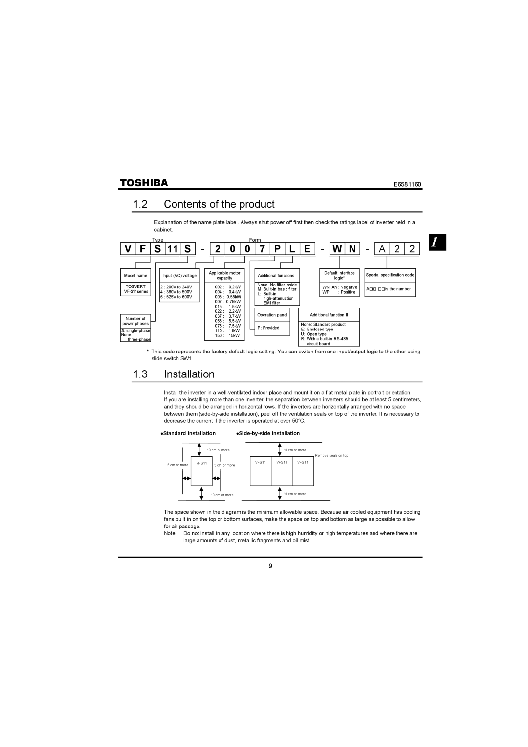
Explanation of the name plate label. Always shut power off first then check the ratings label of inverter held in a cabinet.
Type | Form | 1 |
![]() V
V ![]() F
F ![]() S
S ![]() 11
11 ![]() S
S ![]() -
- ![]() 2
2 ![]() 0
0 ![]() 0
0 ![]() 7
7 ![]() P
P ![]() L
L ![]() E
E ![]() -
- ![]() W
W ![]() N
N ![]() -
- ![]() A
A ![]() 2
2 ![]() 2
2 ![]()
Model name
TOSVERT
Number of power phases
S:
Input (AC) voltage
2 : 200V to 240V
4 : 380V to 500V
6 : 525V to 600V
Applicable motor
capacity
002 : 0.2kW
004 : 0.4kW
005 : 0.55kW
007 : 0.75kW
015 : 1.5kW
022 : 2.2kW
037 : 3.7kW
055 : 5.5kW
075 : 7.5kW
110 : 11kW
150 : 15kW
|
|
|
|
|
|
|
|
Additional functions I |
| Default interface |
| ||||
|
| logic* |
| ||||
|
|
|
|
|
|
| |
|
|
|
|
|
|
|
|
None: No filter inside |
| WN, AN: Negative |
| ||||
M: |
|
| |||||
| WP | : Positive |
| ||||
L: |
|
| |||||
|
|
|
| ||||
|
|
|
| ||||
EMI filter |
|
|
|
| |||
|
|
|
|
|
|
|
|
Operation panel |
|
| Additional function II |
| |||
|
|
|
|
|
| ||
P: Provided |
|
| None: Standard product |
| |||
| E: Enclosed type |
|
| ||||
|
|
|
| U: Open type |
|
| |
|
|
|
| R: With a |
| ||
|
|
|
| circuit board |
|
| |
Special specification code
A:is the number
*This code represents the factory default logic setting. You can switch from one input/output logic to the other using slide switch SW1.
1.3Installation
Install the inverter in a
If you are installing more than one inverter, the separation between inverters should be at least 5 centimeters, and they should be arranged in horizontal rows. If the inverters are horizontally arranged with no space between them
•Standard installation |
5 cm or more
10 cm or more
VFS11 | 5 cm or more |
|
10 cm or more
VFS11 VFS11 VFS11
Remove seals on top
10 cm or more
10 cm or more
The space shown in the diagram is the minimum allowable space. Because air cooled equipment has cooling fans built in on the top or bottom surfaces, make the space on top and bottom as large as possible to allow for air passage.
Note: Do not install in any location where there is high humidity or high temperatures and where there are large amounts of dust, metallic fragments and oil mist.
9