|
|
|
| E6581160 |
|
| Table 1 EMC standards |
| |
|
|
|
|
|
| Category | Subcategory | Product | Test standard and level |
| standards | |||
|
|
|
| |
| Emission | Radiation noise |
| EN55011 Class A Group 1 |
| Transmission noise |
| EN55011 Class A Group 1 | |
|
|
| ||
|
| Static discharge |
| |
|
| Radioactive |
| |
|
| magnetic contactor field | IEC |
|
| Immunity | First transient burst | ||
|
| |||
| Lightning surge |
| ||
|
|
| ||
|
|
| ||
|
| induction/transmission interference |
|
|
|
| Voltage dip/Interruption of power |
| |
Emission standards other than the above are applied to inverters when used in a commercial environment but not an industrial environment.
Category | Subcategory | Product | Test standard and level | |
standards | ||||
|
|
| ||
Emission | Radiation noise | IEC | EN55011 Class B Group 1 | |
Transmission noise | EN55011 Class B Group 1 | |||
|
| |||
|
|
|
6.1.2Measures to satisfy the EMC directive
6
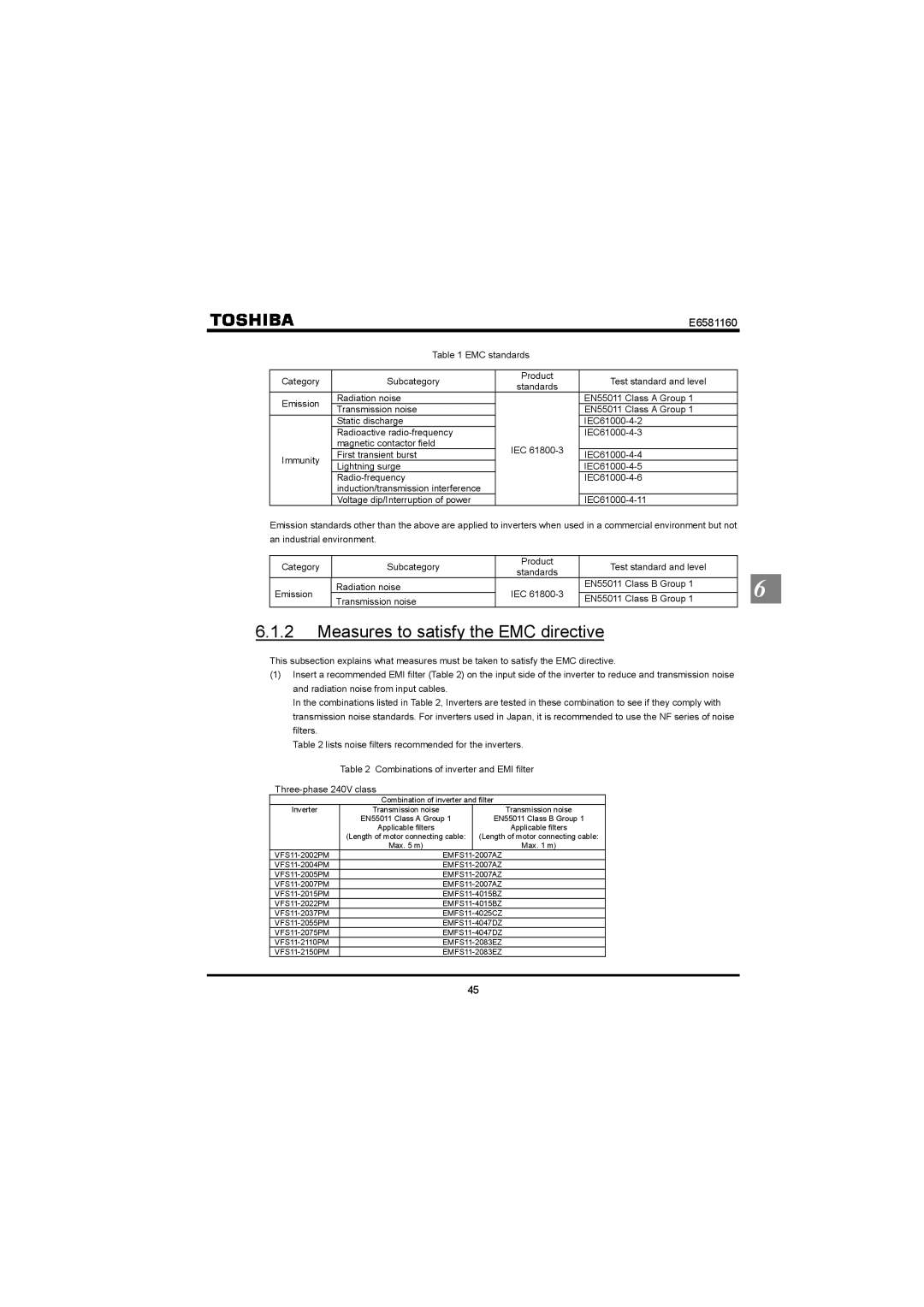
This subsection explains what measures must be taken to satisfy the EMC directive.
(1)Insert a recommended EMI filter (Table 2) on the input side of the inverter to reduce and transmission noise and radiation noise from input cables.
In the combinations listed in Table 2, Inverters are tested in these combination to see if they comply with transmission noise standards. For inverters used in Japan, it is recommended to use the NF series of noise filters.
Table 2 lists noise filters recommended for the inverters.
| Table 2 | Combinations of inverter and EMI filter | ||
|
| |||
|
| Combination of inverter and filter | ||
Inverter |
| Transmission noise |
| Transmission noise |
| EN55011 Class A Group 1 | EN55011 Class B Group 1 | ||
|
| Applicable filters |
| Applicable filters |
| (Length of motor connecting cable: | (Length of motor connecting cable: | ||
|
| Max. 5 m) |
| Max. 1 m) |
|
| EMFS11 | ||
|
| |||
|
| |||
|
| |||
|
| |||
|
| |||
|
| |||
|
| |||
|
| |||
|
| |||
|
| |||
45
