E6581160
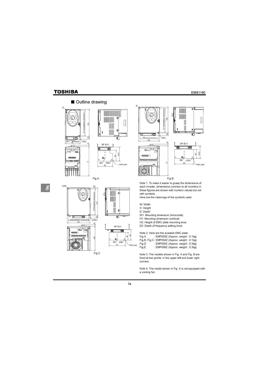
QOutline drawing
f5
121.5(Installation dimension) | 130 |
|
| 15 |
|
|
60 | (Installation | R2.5 |
|
|
dimension) |
|
| ||
| 72 | 8 | ||
|
|
| ||
|
| D | M5 | |
|
|
| ||
|
|
|
| 68 |
|
|
| Fig.A |
|
f5
121.5(Installation dimension) | 130 |
| 13 |
93(Installation dimension) | R2.5 |
| 105 |
| 8 |
50 | 64.5 |
| D |
| EMC plate |
| Fig.B |
VF-S11
M5
95
|
|
|
|
50 |
| 64.5 | |
| |||
|
|
|
|
EMC plate
8 | 65 | |
|
|
| 157(Installation dimension) | 170 |
|
| 14 |
126(Installation dimension) | ||
140 | 8 |
|
|
| |
| 150 |
|
Fig.C
M5
95
48 |
| 62 |
|
|
|
|
| ||
|
|
|
|
|
|
| EMC plate | ||
Note 1. To make it easier to grasp the dimensions of each inverter, dimensions common to all inverters in these figures are shown with numeric values but not with symbols.
Here are the meanings of the symbols used.
W:Width
H:Height
D:Depth
W1: Mounting dimension (horizontal)
H1: Mounting dimension (vertical)
H2: Height of EMC plate mounting area
D2: Depth of frequency setting knob
Note 2. Here are the avaiable EMC plate
Fig.A : EMP003Z (Approx. weight : 0.1kg)
Fig.B, Fig.C : EMP004Z (Approx. weight : 0.1kg)
Fig.D | : EMP005Z (Approx. weight : 0.3kg) |
Fig.E | : EMP006Z (Approx. weight : 0.3kg) |
Note 3. The models shown in Fig. A and Fig. B are fixed at two points: in the upper left and lower right corners.
Note 4. The model shown in Fig. A is not equipped with a cooling fan.
74