|
|
|
|
| E6581160 | |
|
|
|
|
|
|
|
| Terminal | Input/output | Function | Electrical | Inverter internal circuits | |
| symbol | specifications | ||||
|
|
|
|
| ||
2
RY RC
Output
Multifunction programmable relay contact output.
Standard default settings detect and output
Multifunction output terminals to which two different functions can be assigned.
:at resistance load
+24V
RY ![]()
![]()
![]() RY
RY ![]() RC
RC ![]()
![]()
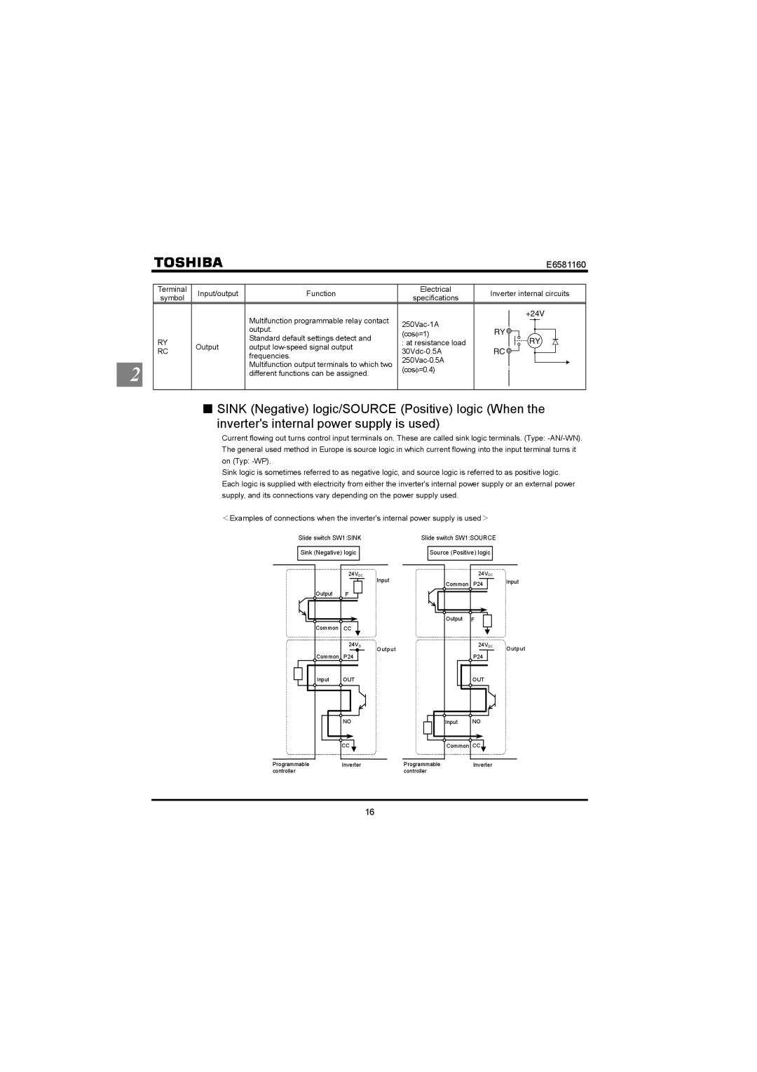
QSINK (Negative) logic/SOURCE (Positive) logic (When the
inverter's internal power supply is used)
Current flowing out turns control input terminals on. These are called sink logic terminals. (Type:
Sink logic is sometimes referred to as negative logic, and source logic is referred to as positive logic. Each logic is supplied with electricity from either the inverter's internal power supply or an external power supply, and its connections vary depending on the power supply used.
<Examples of connections when the inverter's internal power supply is used>
Slide switch SW1:SINK | Slide switch SW1:SOURCE | |||
|
|
|
|
|
Sink (Negative) logic |
|
| Source (Positive) logic |
|
|
|
|
|
|
| 24VDC | Input | |
|
| ||
Output | F |
| |
Common | CC |
| |
| 24VD | Output | |
Common | P24 | ||
| |||
Input | OUT |
| |
| NO |
| |
| CC |
|
| 24VDC |
|
Common | P24 | Input |
| ||
Output | F |
|
| 24VDC | Output |
|
| |
| P24 |
|
| OUT |
|
Input | NO |
|
Common CC |
| |
Programmable | Inverter | Programmable | Inverter |
controller |
| controller |
|
16