|
|
|
|
|
|
| E6581160 |
|
|
|
|
|
|
|
|
|
|
|
|
|
| Capacity of |
|
| Wire size (See Note 4) |
|
|
| |
| Voltage class | applicable | Inverter model | Power circuit | DC reactor | Braking resistor/ | Earth cable |
|
|
| (mm2) (Note 1.) | (optional) (mm2) | Braking unit | (mm2) |
|
| |||
|
| motor (kW) |
|
|
| (optional) (mm2) |
|
|
|
|
| 0.4 | 2.0 (2.0) | 2.0 | 2.0 | 3.5 |
|
| |
|
| 0.75 | 2.0 (2.0) | 2.0 | 2.0 | 3.5 |
|
| |
|
| 1.5 | 2.0 (2.0) | 2.0 | 2.0 | 3.5 |
|
| |
| 2.2 | 2.0 (2.0) | 2.0 | 2.0 | 3.5 |
|
| ||
| 4.0 | 2.0 (2.0) | 2.0 | 2.0 | 3.5 |
|
| ||
| 500V class |
|
| ||||||
| 5.5 | 2.0 (2.0) | 3.5 | 2.0 | 3.5 |
|
| ||
|
|
|
| ||||||
|
| 7.5 | 3.5 (2.0) | 5.5 | 2.0 | 3.5 |
| 2 | |
|
| 11 | 5.5 (2.0) | 8.0 | 2.0 | 5.5 |
| ||
|
| 15 | 8.0 (5.5) | 14 | 3.5 | 5.5 |
| ||
|
| 0.75 | 2.0 | 2.0 | 2.0 | 3.5 |
|
| |
|
| 1.5 | 2.0 | 2.0 | 2.0 | 3.5 |
|
| |
| 2.2 | 2.0 | 2.0 | 2.0 | 3.5 |
|
| ||
| 4.0 | 2.0 | 2.0 | 2.0 | 3.5 |
|
| ||
| 600V class | 5.5 | 2.0 | 2.0 | 2.0 | 3.5 |
|
| |
|
| 7.5 | 2.0 | 2.0 | 2.0 | 3.5 |
|
| |
|
| 11 | 3.5 | 3.5 | 2.0 | 3.5 |
|
| |
|
| 15 | 5.5 | 5.5 | 2.0 | 5.5 |
|
| |
Note 1: Sizes of the wires connected to the input terminals R/L1, S/L2 and T/L3 and the output terminals U/T1, V/T2 and W/T3 when the length of each wire does not exceed 30m.
The numeric values in parentheses refer to the sizes of wires to be used when a DC reactor is connected. Note 2: For the control circuit, use shielded wires 0.75 mm2 or more in diameter.
Note 3: For grounding, use a cable with a size equal to or larger than the above.
Note 4: The wire sizes specified in the above table apply to HIV wires (cupper wires shielded with an insulator with a maximum allowable temperature of 75°C) used at an ambient temperature of 50°C or less.
Note 5: If there is a need to bring the inverter into UL compliance, use wires specified in Chapter 6.
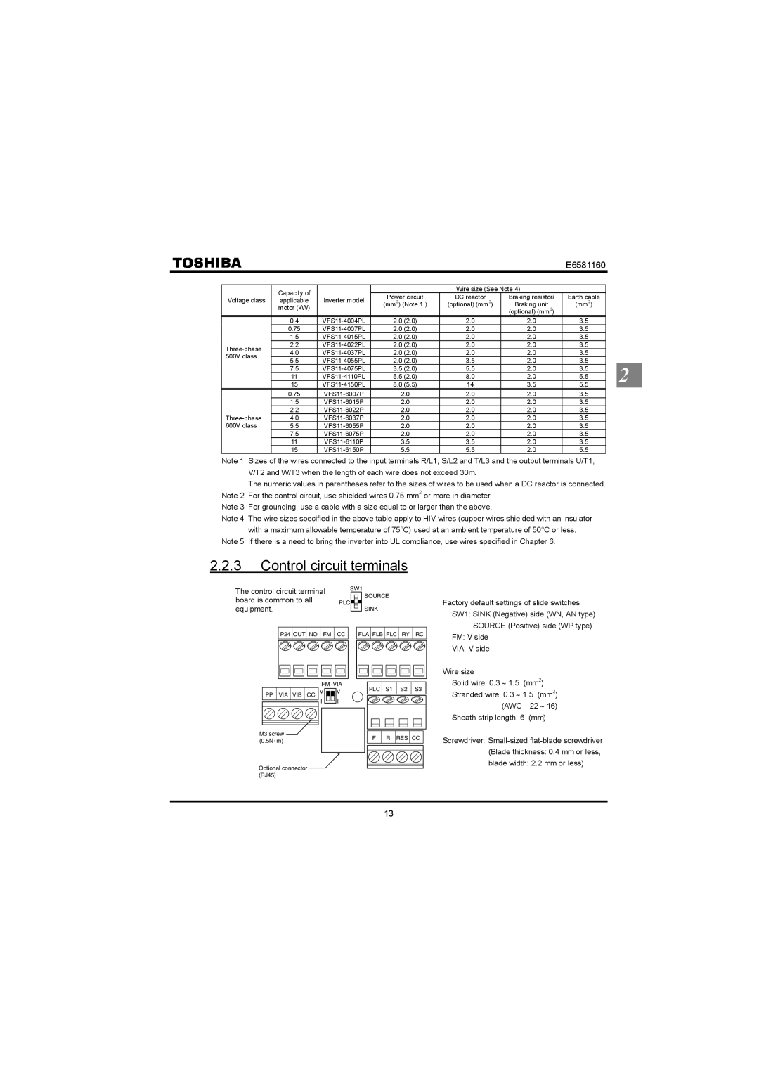
2.2.3Control circuit terminals
The control circuit terminal | SW1 | |
board is common to all | PLC | SOURCE |
| ||
equipment. |
| SINK |
| ||
Factory default settings of slide switches SW1: SINK (Negative) side (WN, AN type)
SOURCE (Positive) side (WP type)
P24 OUT NO FM CC |
FM VIA
PPVIA VIB CC V ![]()
![]() V
V ![]() I
I ![]() I
I
FLA FLB FLC | RY | RC |
PLC S1 | S2 | S3 |
FM: V side
VIA: V side
Wire size
Solid wire: 0.3 ∼ 1.5 (mm2)
Stranded wire: 0.3 ∼ 1.5 (mm2) (AWG 22 ∼ 16)
Sheath strip length: 6 (mm)
M3 screw | F | R | RES | CC |
(0.5N m) |
Optional connector (RJ45)
Screwdriver:
13