B. Clearances
| B | |
| A | |
Upper front can be |
|
|
covered with | 0 in. to level | |
material or removed | of standoffs | |
and replaced with |
|
|
|
| |
|
| |
material. |
|
|
|
| |
|
|
|
Object |
| 36 in. |
| ||
|
| |
Combustible |
| (914 mm) |
|
| |
|
|
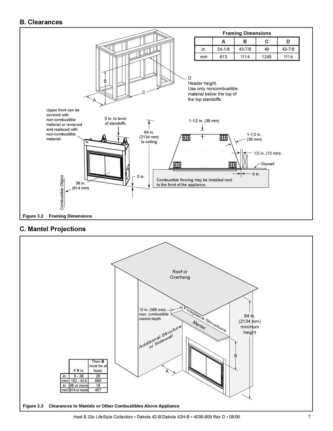
Figure 3.2 Framing Dimensions
|
| Framing Dimensions |
| ||
|
| A | B | C | D |
| in. | 49 | |||
| mm | 613 | 1114 | 1245 | 1114 |
| D |
|
|
|
|
| Header height. |
|
|
|
|
C | Use only noncombustible |
|
|
| |
material below the top of |
|
|
| ||
| the top standoffs. |
|
|
| |
|
|
|
| ||
84 in. |
|
|
| ||
(2134 mm) |
|
| |||
| (38 mm) |
| |||
to ceiling |
|
| |||
|
|
|
| ||
|
|
|
| 1/2 in. (13 mm) |
|
|
|
|
| Drywall |
|
0 in. |
|
|
| 0 in. |
|
Combustible flooring may be installed next |
|
|
| ||
|
|
|
| ||
| to the front of the appliance. |
|
|
|
|
C. Mantel Projections
Roof or
Overhang
12 in. (305 mm) ![]()
![]() max. combustible mantel depth
max. combustible mantel depth
|
| Structure |
|
| Sidewall |
| nal | |
tio |
| |
Addior |
|
|
Fireplace | Structure | |
Mantel | ||
|
84in.
(2134 mm)
minimum
height
B
|
| Then B |
| If A is: | must be at |
| least: | |
in. | 6 - 36 | 26 |
mm | 152 - 914 | 660 |
in. | 36 or more | 18 |
mm | 914 or more | 457 |
A
Figure 3.3 Clearances to Mantels or Other Combustibles Above Appliance
Heat & Glo LifeStyle Collection • Dakota | 7 |
