PREPARE THE UNIT
STEPS 1 THRU 3 - UNITS WITH HEATERS ONLY
1.Make sure the heater assembly is unplugged from the RED receptacle.
2.Loosen the two retaining screws on the inside of the heater discharge opening. Place a screwdriver tip between the outer wall of the discharge open- ing and the fan housing. Gently pry outward until the exhaust discharge slips off the support lip on the outer housing. (FIG. 1)
3.Unhook hinge pins and lift heater assembly out of housing. (FIG. 2)
4.Unplug the fan assembly from the BLACK recep- tacle. Remove the plastic bag and set it aside.
5.Remove the mounting screw and carefully lift the fan assembly out of the housing. (FIG. 3)
6.Refer to the wiring diagram of your unit on the next page. Remove appropriate knockout(s) by inserting a screwdriver blade into slots and bending it back and forth to break tabs. (FIG. 4)
7.Insert the adjustable mounting brackets into the bracket channels on the housing. (FIG. 5)
INSTALL THE UNIT
8.For best results, choose a location which allows fan to be vented outside with the shortest possible duct run and the fewest number of elbows.
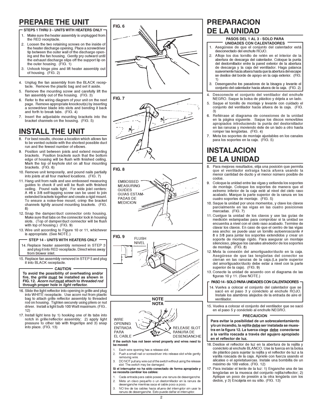
9.Position unit between joists and extend mounting brackets. Position brackets such that the bottom edge of housing will be flush with finished ceiling. Mark the top of keyhole slot on all four mounting brackets. (FIG. 6)
10.Remove unit temporarily, and pound nails partially into joists at all four marked locations. (FIG. 7)
11.Hang unit from nails and use embossed measuring guides to check if unit will be flush with finished ceiling. Pound nails tight. For wide joist centers: A #8 x 3/8 self-tapping screw can be used to join extended brackets together and create a rigid mount. To ensure a noise-free mount, crimp the bracket channels tightly around mounting brackets. (FIG. 8)
12.Snap the damper/duct connector onto housing. Make sure that tabs on the connector lock in housing slots. (Top of damper/duct connector will be flush with top of housing.) (FIG. 9)
13.Wire unit according to Figure 10 or 11, whichever is appropriate. (See NOTE.)
STEP 14 - UNITS WITH HEATERS ONLY
14.Replace heater assembly removed in STEP 3 and plug it into RED receptacle. Direct wires away from blower inlet.
15.Replace fan assembly removed in STEP 5 and plug it into BLACK receptacle.
CAUTION
To avoid the possibility of overheating and/or fire, the grille must be installed as shown in FIG. 12. Acorn nut must attach to threaded rod through proper hole in light reflector.
16.Slide the light reflector into opening in grille and plug into WHITE receptacle. Use acorn nut from plastic bag to attach grille reflector assembly to threaded rod on housing. Tighten securely using pliers or nut driver. Install a light bulb 100 Watt maximum. (FIG.. 12)
17.Install light lens by 1) hooking one of its tabs into notch in grille/reflector assembly; 2) apply light pressure to other tab with fingertips and 3) snap into place. (FIG. 13)
FIG. 6
FIG. 7
FIG. 8
EMBOSSED MEASURING GUIDES guias estam- padas de medicion
| NOTE | |
WIRE | NOTA | |
| |
OPENING | | |
entrada | | RELEASE SLOT |
para | | ranura de |
el cable | | desenganche |
If the switch has not been wired properly and wires need to be moved:
1.Each wire opening has a release slot.
2.Push a small nail or screwdriver into release slot while gently removing wire.
3.DO NOT pull any wire out of the switch without using the release slot. The switch may be damaged.
Si el interruptor no ha sido conectado de forma apropiada y se necesita cambiar los cables:
1.Cada entrada para cable posee una ranura de desenganche.
2.Meta un clavo pequeño o un destornillador en la ranura de desenganche mientras saca el cable poco a poco.
3.NO tire de los cables hacia afuera del interruptor sin usar la ranura de desenganche. Esto puede dañar el interruptor.
PREPARACION
DE LA UNIDAD
PASOS DEL 1 AL 3 - SOLO PARA
UNIDADES CON CALENTADORES
1.Asegúrese de que el conjunto del calentador está desconectado del enchufe ROJO.
2.Afloje los dos tornillo de retén en el interior de la abertura de descarga del calentador. Coloque la punta del destornillador entre la pared exterior de la abertura de descarga y la caja del ventilador. Haga palanca suavemente hacia afuera hasta que la abertura del escape se deslice del borde de apoyo en la caja exterior. (FIG. 1)
3.Desenganche los pasadores de la bisagra y levante el conjunto del calentador hacia afuera de la caja. (FIG. 2)
4.Desconecte el conjunto del ventilador del enchufe NEGRO. Saque la bolsa de plástico y déjela a un lado.
5.Saque el tornillo de montaje y levante con cuidado el conjunto del ventilador hacia afuera de la caja. (FIG. 3)
6.Refiérase al diagrama de conexiones de la unidad en la página siguiente. Saque los discos removibles apropiados introduciendo la punta del destornillador en las ranuras y moviendo éste de un lado a otro hasta romper las lengüetas. (FIG. 4)
7.Meta los soportes de montaje ajustables en los canales para los soportes en la caja. (FIG. 5)
INSTALACION
DE LA UNIDAD
8.Para mejores resultados, elija una posición que permita que el ventilador extraiga hacia afuera usando la menor cantidad de ducto y el menor número posible de codos.
9.Coloque la unidad entre las vigas y extienda los soportes de montaje. Coloque los soportes de manera que el extremo inferior de la caja esté al nivel del cielo raso acabado. Marque la parte superior de la ranura en los cuatro soportes de montaje. (FIG. 5)
10.Saque la unidad por unos momentos, y clave los clavos parcialmente en las vigas en las cuatro posiciones marcadas. (FIG. 7)
11.Cuelgue la unidad de los clavos y use las guías de medición estampadas para comprobar si la unidad se encuentra a nivel con el cielo raso acabado. Termine de clavar los clavos. En caso de que el centro de las vigas sea ancho: se puede usar un tornillo autoenroscante # 8 x 3/8 para juntar los soportes extendidos y crear un soporte de montaje rígido. Para asegurar un montaje silencioso, pliegue los canales alrededor de los soportes de montaje. (FIG. 8)
12.Meta la conexión del amortiguador/ducto en la caja. Asegúrese de que las lengüetas del conector se cierran en las ranuras de la caja.(La parte superior del amortiguador/ducto debe estar a nivel con la parte superior de la caja). (FIG. 9)
13.Conecte la unidad de acuerdo con el diagrama de las figuras 10 y 11. (See NOTE.)
PASO 14 - SOLO PARA UNIDADES CON CALENTADORES
14.Vuelva a colocar el conjunto del calentador que se sacó en el paso 3 y conéctelo al enchufe ROJO.
Instale los alambres alejados de la entrada de aire el ventilador.
15.Vuelva a colocar el conjunto del ventilador que se sacó en el paso 5 y conéctelo al enchufe NEGRO.
PRECAUCION
Para evitar la posibilidad de un sobrecalentamiento y/o un incendio, la rejilla debe ser instalada se mues- tra en la figura 12. La tuerca ciega debe conectarse a la varilla roscada a través del agujero apropiado en el reflector de luz.
16.Deslice el reflector de luz en la abertura de la rejilla y conéctelo al enchufe BLANCO. Use la tuerca en la bolsa de plástico para sujetar la rejilla y el reflector de luz a la varilla roscada de la caja. Apriete con fuerza usando el alicates o el aprietatuercas. Instale una bombilla de un máximo de 100 vatios. (FIG. 12)
17.Para instalar el lente de la luz: 1) Enganche una de las lengüetas en la muesca del conjunto rejilla/reflector; 2) Aplique un poco de presión a la otra lengûeta con los dedos, y 3) Encájela en su sitio. (FIG. 13)