116B
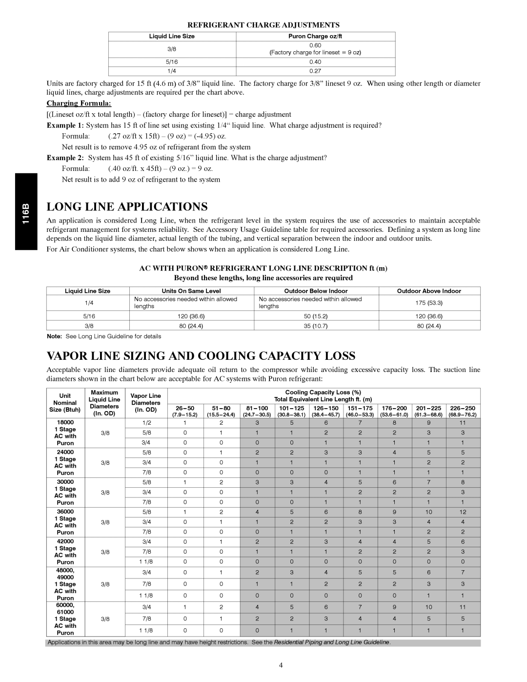
REFRIGERANT CHARGE ADJUSTMENTS
Liquid Line Size | Puron Charge oz/ft | |
|
| |
3/8 | 0.60 | |
(Factory charge for lineset = 9 oz) | ||
| ||
|
| |
5/16 | 0.40 | |
|
| |
1/4 | 0.27 | |
|
|
Units are factory charged for 15 ft (4.6 m) of 3/8” liquid line. The factory charge for 3/8” lineset 9 oz. When using other length or diameter liquid lines, charge adjustments are required per the chart above.
Charging Formula:
[(Lineset oz/ft x total length) – (factory charge for lineset)] = charge adjustment
Example 1: System has 15 ft of line set using existing 1/4“ liquid line. What charge adjustment is required?
Formula: | (.27 oz/ft x 15ft) – (9 oz) = |
Net result is to remove 4.95 oz of refrigerant from the system
Example 2: System has 45 ft of existing 5/16” liquid line. What is the charge adjustment?
Formula: | (.40 oz/ft. x 45ft) – (9 oz.) = 9 oz. |
Net result is to add 9 oz of refrigerant to the system
LONG LINE APPLICATIONS
An application is considered Long Line, when the refrigerant level in the system requires the use of accessories to maintain acceptable refrigerant management for systems reliability. See Accessory Usage Guideline table for required accessories. Defining a system as long line depends on the liquid line diameter, actual length of the tubing, and vertical separation between the indoor and outdoor units.
For Air Conditioner systems, the chart below shows when an application is considered Long Line.
AC WITH PURONr REFRIGERANT LONG LINE DESCRIPTION ft (m)
Beyond these lengths, long line accessories are required
Liquid Line Size | Units On Same Level | Outdoor Below Indoor | Outdoor Above Indoor | |
1/4 | No accessories needed within allowed | No accessories needed within allowed | 175 (53.3) | |
lengths | lengths | |||
|
| |||
|
|
|
| |
5/16 | 120 (36.6) | 50 (15.2) | 120 (36.6) | |
3/8 | 80 (24.4) | 35 (10.7) | 80 (24.4) |
Note: See Long Line Guideline for details
VAPOR LINE SIZING AND COOLING CAPACITY LOSS
Acceptable vapor line diameters provide adequate oil return to the compressor while avoiding excessive capacity loss. The suction line diameters shown in the chart below are acceptable for AC systems with Puron refrigerant:
Unit | Maximum | Vapor Line |
|
|
| Cooling Capacity Loss (%) |
|
|
| |||
Liquid Line |
|
|
| Total Equivalent Line Length ft. (m) |
|
|
| |||||
Nominal | Diameters |
|
|
|
|
|
| |||||
Diameters |
|
|
|
|
|
|
|
|
| |||
Size (Btuh) | (In. OD) | |||||||||||
(In. OD) | ||||||||||||
|
| |||||||||||
18000 |
| 1/2 | 1 | 2 | 3 | 5 | 6 | 7 | 8 | 9 | 11 | |
1 Stage | 3/8 | 5/8 | 0 | 1 | 1 | 1 | 2 | 2 | 2 | 3 | 3 | |
AC with | ||||||||||||
Puron |
| 3/4 | 0 | 0 | 0 | 0 | 1 | 1 | 1 | 1 | 1 | |
24000 |
| 5/8 | 0 | 1 | 2 | 2 | 3 | 3 | 4 | 5 | 5 | |
1 Stage | 3/8 | 3/4 | 0 | 0 | 1 | 1 | 1 | 1 | 1 | 2 | 2 | |
AC with | ||||||||||||
Puron |
| 7/8 | 0 | 0 | 0 | 0 | 0 | 1 | 1 | 1 | 1 | |
30000 |
| 5/8 | 1 | 2 | 3 | 3 | 4 | 5 | 6 | 7 | 8 | |
1 Stage | 3/8 | 3/4 | 0 | 0 | 1 | 1 | 1 | 2 | 2 | 2 | 3 | |
AC with | ||||||||||||
Puron |
| 7/8 | 0 | 0 | 0 | 0 | 1 | 1 | 1 | 1 | 1 | |
36000 |
| 5/8 | 1 | 2 | 4 | 5 | 6 | 8 | 9 | 10 | 12 | |
1 Stage | 3/8 | 3/4 | 0 | 1 | 1 | 2 | 2 | 3 | 3 | 4 | 4 | |
AC with | ||||||||||||
Puron |
| 7/8 | 0 | 0 | 0 | 1 | 1 | 1 | 1 | 2 | 2 | |
42000 |
| 3/4 | 0 | 1 | 2 | 2 | 3 | 4 | 4 | 5 | 6 | |
1 Stage | 3/8 | 7/8 | 0 | 0 | 1 | 1 | 1 | 2 | 2 | 2 | 3 | |
AC with | ||||||||||||
Puron |
| 1 1/8 | 0 | 0 | 0 | 0 | 0 | 0 | 0 | 0 | 0 | |
48000, |
| 3/4 | 0 | 1 | 2 | 3 | 4 | 5 | 5 | 6 | 7 | |
49000 |
| |||||||||||
|
|
|
|
|
|
|
|
|
|
| ||
| 7/8 | 0 | 0 | 1 | 1 | 2 | 2 | 2 | 3 | 3 | ||
1 Stage | 3/8 | |||||||||||
AC with |
| 1 1/8 | 0 | 0 | 0 | 0 | 0 | 0 | 0 | 1 | 1 | |
Puron |
| |||||||||||
|
|
|
|
|
|
|
|
|
|
| ||
60000, |
| 3/4 | 1 | 2 | 4 | 5 | 6 | 7 | 9 | 10 | 11 | |
61000 |
| |||||||||||
|
|
|
|
|
|
|
|
|
|
| ||
1 Stage | 3/8 | 7/8 | 0 | 1 | 2 | 2 | 3 | 4 | 4 | 5 | 5 | |
AC with |
| 1 1/8 | 0 | 0 | 0 | 1 | 1 | 1 | 1 | 1 | 1 | |
Puron |
| |||||||||||
|
|
|
|
|
|
|
|
|
|
|
| |
Applications in this area may be long line and may have height restrictions. See the Residential Piping and Long Line Guideline.
4