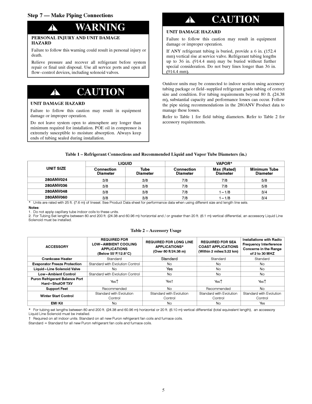
280ANV specifications
The Bryant 280ANV is a highly efficient air conditioning unit designed for residential use, providing homeowners with reliable cooling performance while maintaining energy efficiency. One of the standout features of the Bryant 280ANV is its two-stage compressor, which allows for variable speed operation. This means that the unit can adjust its cooling output to match the current demand for indoor comfort, leading to more consistent temperatures and increased energy savings.The Bryant 280ANV also boasts an impressive SEER (Seasonal Energy Efficiency Ratio) rating, which indicates its energy efficiency. Typically, this model achieves a SEER rating of up to 20, making it a strong contender in the market for those looking to reduce their energy bills without sacrificing comfort. This level of efficiency not only results in lower monthly costs but also contributes to a reduced environmental footprint.
Another key technology featured in the Bryant 280ANV is its advanced, variable-speed blower motor. This motor helps to operate quietly while ensuring optimal airflow throughout the home. The quiet operation of the 280ANV means that it can deliver cooling without disturbing your daily life, making it an excellent choice for bedrooms or other quiet spaces.
The unit is also designed with durability in mind. Its cabinet is constructed from high-quality, weather-resistant materials that protect against harsh outdoor conditions. This ensures longevity and reliable performance over the years. Furthermore, the Bryant 280ANV includes a protected scroll compressor that adds an extra layer of reliability and enhances the unit's overall efficiency.
Installation of the Bryant 280ANV can be completed by a qualified HVAC professional, who can ensure that the system is set up to operate at peak performance. Additional features, such as the built-in Wi-Fi capability, allow homeowners to connect the unit to smart home systems for enhanced control and convenience.
In conclusion, the Bryant 280ANV combines energy efficiency with advanced technology to provide effective cooling solutions for residential spaces. With its two-stage compressor, high SEER rating, quiet operation, and durable construction, it meets the needs of modern homeowners who value comfort, efficiency, and reliability. Overall, the Bryant 280ANV stands out as a quality choice for those seeking a dependable air conditioning system.

