286A / 288A
NOTE: Install branch circuit disconnect of adequate size per NEC to handle unit starting current. Locate disconnect within sight from and readily accessible from unit, per Section
Route Ground and Power Wires
Remove access panel to gain access to unit wiring. Extend wires from disconnect through power wiring hole provided and into unit control box.
!WARNING
ELECTRICAL SHOCK HAZARD
Failure to follow this warning could result in personal injury or death.
The unit cabinet must have an uninterrupted or unbroken ground to minimize personal injury if an electrical fault should occur. The ground may consist of electrical wire or metal conduit when installed in accordance with existing electrical codes.
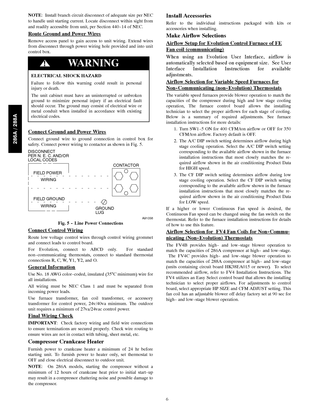
Connect Ground and Power Wires
Connect ground wire to ground connection in control box for safety. Connect power wiring to contactor as shown in Fig. 5.
DISCONNECT
PER N. E. C. AND/OR
LOCAL CODES
Install Accessories
Refer to the individual instructions packaged with kits or accessories when installing.
Make Airflow Selections
Airflow Setup for Evolution Control Furnace of FE Fan coil (communicating)
When using an Evolution User Interface, airflow is automatically selected based on equipment size. See User Interface Installation Instructions for available adjustments.
Airflow Selection for Variable Speed Furnaces for
The variable speed furnaces provide blower operation to match the capacities of the compressor during high and low stage cooling operation, The furnace control board allows the installing technician to select the proper airflows for each stage of cooling. Below is a summary of required adjustments. See furnace installation instructions for more details:
1. | Turn |
| CFM/ton airflow. Factory default is OFF. |
2. | The A/C DIP switch setting determines airflow during high |
| stage cooling operation. Select the A/C DIP switch setting |
| corresponding to the available airflow shown in the furnace |
| installation instructions that most closely matches the re- |
| quired airflow shown in the air conditioning Product Data |
FIELD POWER
WIRING
FIELD GROUND
WIRING
CONTACTOR |
GROUND
LUG
A91056
for HIGH speed. |
3. The CF DIP switch setting determines airflow during low |
stage cooling operation. Select the CF DIP switch setting |
corresponding to the available airflow shown in the furnace |
installation instructions that most closely matches the re- |
quired airflow shown in the air conditioning Product Data |
for LOW speed. |
If a higher or lower Continuous Fan speed is desired, the Continuous Fan speed can be changed using the fan switch on the thermostat. Refer to the furnace installation instructions for details
Fig. 5 - Line Power Connections
Connect Control Wiring
Route low voltage control wires through control wiring grommet and connect leads to control board.
For Evolution, connect to ABCD only. For standard
General Information
Use No. 18 AWG
All wiring must be NEC Class 1 and must be separated from incoming power leads.
Use furnace transformer, fan coil transformer, or accessory transformer for control power, 24v/40va minimum. The outdoor unit requires a minimum of 27va/24vac control power.
Final Wiring Check
IMPORTANT: Check factory wiring and field wire connections to ensure terminations are secured properly. Check wire routing to ensure wires are not in contact with tubing, sheet metal, etc.
Compressor Crankcase Heater
Furnish power to crankcase heater a minimum of 24 hr before starting unit. To furnish power to heater only, set thermostat to OFF and close electrical disconnect to outdoor unit.
NOTE: On 286A models, starting the compressor without a minimum of 12 hours of crankcase heat prior to initial
of how to use this feature.
Airflow Selection for FV4 Fan Coils for
nicating
The FV4B provides high- and
6