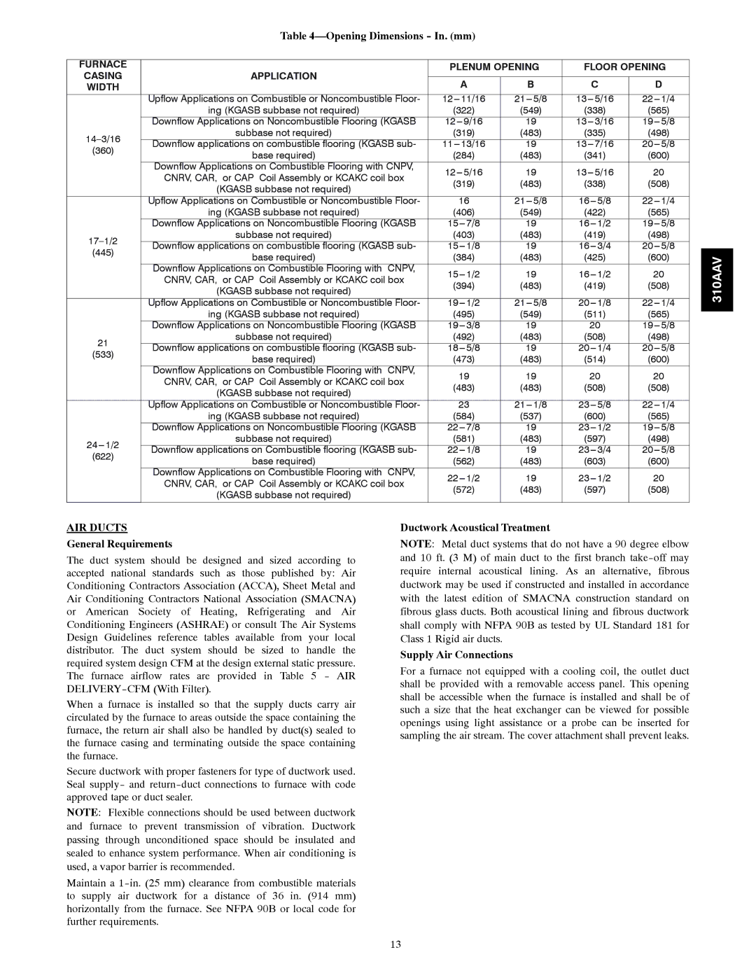
Table 4—Opening Dimensions - In. (mm)


FURNACE


PLENUM OPENING

FLOOR OPENING

CASING

APPLICATION


WIDTH


A

B

C

D


Upflow Applications on Combustible or Noncombustible Floor-

12--- 11/16

21--- 5/8

13--- 5/16

22--- 1/4


ing (KGASB subbase not required)

(322)

(549)

(338)

(565)


Downflow Applications on Noncombustible Flooring (KGASB

12--- 9/16

19

13--- 3/16

19--- 5/8

14–3/16

subbase not required)

(319)

(483)

(335)

(498)

Downflow applications on combustible flooring (KGASB sub-

11--- 13/16

19

13--- 7/16

20--- 5/8

(360)

base required)

(284)

(483)

(341)

(600)


Downflow Applications on Combustible Flooring with CNPV,

12--- 5/16

19

13--- 5/16

20


CNRV, CAR, or CAP Coil Assembly or KCAKC coil box


(319)

(483)

(338)

(508)


(KGASB subbase not required)


Upflow Applications on Combustible or Noncombustible Floor-

16

21--- 5/8

16--- 5/8

22--- 1/4


ing (KGASB subbase not required)

(406)

(549)

(422)

(565)


Downflow Applications on Noncombustible Flooring (KGASB

15--- 7/8

19

16--- 1/2

19--- 5/8

17–1/2

subbase not required)

(403)

(483)

(419)

(498)

Downflow applications on combustible flooring (KGASB sub-

15--- 1/8

19

16--- 3/4

20--- 5/8

(445)

base required)

(384)

(483)

(425)

(600)


Downflow Applications on Combustible Flooring with CNPV,

15--- 1/2

19

16--- 1/2

20


CNRV, CAR, or CAP Coil Assembly or KCAKC coil box


(394)

(483)

(419)

(508)


(KGASB subbase not required)


Upflow Applications on Combustible or Noncombustible Floor-

19--- 1/2

21--- 5/8

20--- 1/8

22--- 1/4


ing (KGASB subbase not required)

(495)

(549)

(511)

(565)


Downflow Applications on Noncombustible Flooring (KGASB

19--- 3/8

19

20

19--- 5/8

21

subbase not required)

(492)

(483)

(508)

(498)

Downflow applications on combustible flooring (KGASB sub-

18--- 5/8

19

20--- 1/4

20--- 5/8

(533)

base required)

(473)

(483)

(514)

(600)


Downflow Applications on Combustible Flooring with CNPV,

19

19

20

20


CNRV, CAR, or CAP Coil Assembly or KCAKC coil box


(483)

(483)

(508)

(508)


(KGASB subbase not required)


Upflow Applications on Combustible or Noncombustible Floor-

23

21--- 1/8

23--- 5/8

22--- 1/4


ing (KGASB subbase not required)

(584)

(537)

(600)

(565)


Downflow Applications on Noncombustible Flooring (KGASB

22--- 7/8

19

23--- 1/2

19--- 5/8

24--- 1/2

subbase not required)

(581)

(483)

(597)

(498)

Downflow applications on Combustible flooring (KGASB sub-

22--- 1/8

19

23--- 3/4

20--- 5/8

(622)

base required)

(562)

(483)

(603)

(600)


Downflow Applications on Combustible Flooring with CNPV,

22--- 1/2

19

23--- 1/2

20


CNRV, CAR, or CAP Coil Assembly or KCAKC coil box


(572)

(483)

(597)

(508)


(KGASB subbase not required)


310AAV

AIR DUCTS

General Requirements

The duct system should be designed and sized according to accepted national standards such as those published by: Air Conditioning Contractors Association (ACCA), Sheet Metal and Air Conditioning Contractors National Association (SMACNA) or American Society of Heating, Refrigerating and Air Conditioning Engineers (ASHRAE) or consult The Air Systems Design Guidelines reference tables available from your local distributor. The duct system should be sized to handle the required system design CFM at the design external static pressure. The furnace airflow rates are provided in Table 5 - AIR DELIVERY-CFM (With Filter).

When a furnace is installed so that the supply ducts carry air circulated by the furnace to areas outside the space containing the furnace, the return air shall also be handled by duct(s) sealed to the furnace casing and terminating outside the space containing the furnace.

Secure ductwork with proper fasteners for type of ductwork used. Seal supply- and return-duct connections to furnace with code approved tape or duct sealer.

NOTE: Flexible connections should be used between ductwork and furnace to prevent transmission of vibration. Ductwork passing through unconditioned space should be insulated and sealed to enhance system performance. When air conditioning is used, a vapor barrier is recommended.

Maintain a 1-in. (25 mm) clearance from combustible materials to supply air ductwork for a distance of 36 in. (914 mm) horizontally from the furnace. See NFPA 90B or local code for further requirements.

Ductwork Acoustical Treatment

NOTE: Metal duct systems that do not have a 90 degree elbow and 10 ft. (3 M) of main duct to the first branch take-off may require internal acoustical lining. As an alternative, fibrous ductwork may be used if constructed and installed in accordance with the latest edition of SMACNA construction standard on fibrous glass ducts. Both acoustical lining and fibrous ductwork shall comply with NFPA 90B as tested by UL Standard 181 for Class 1 Rigid air ducts.

Supply Air Connections

For a furnace not equipped with a cooling coil, the outlet duct shall be provided with a removable access panel. This opening shall be accessible when the furnace is installed and shall be of such a size that the heat exchanger can be viewed for possible openings using light assistance or a probe can be inserted for sampling the air stream. The cover attachment shall prevent leaks.

13

Page 13
Image 13
Bryant 310AAV Opening Dimensions In. mm, AIR Ducts, General Requirements, Furnace Plenum Opening Floor Opening Casing

310AAV specifications

The Bryant 310AAV and 310JAV are high-efficiency air conditioning and heating systems designed for residential and light commercial applications. These models embody Bryant's commitment to delivering reliable comfort solutions while prioritizing energy efficiency and performance.

One of the standout features of the Bryant 310AAV and 310JAV is their impressive Seasonal Energy Efficiency Ratio (SEER) ratings. The higher the SEER, the more efficient the unit is in using electricity to cool your space. The Bryant 310AAV boasts a SEER rating of up to 16, while the 310JAV offers a slightly lower rating. This efficiency translates into cost savings on monthly energy bills while ensuring indoor comfort throughout the year.

Both models utilize advanced technologies, including two-stage heating and cooling capabilities. This means that the systems can adjust their operation based on the heating or cooling needs of a space, providing optimal temperature control while reducing energy waste. The two-stage operation also contributes to quieter operation levels, making these units suitable for residential settings where noise is a concern.

The 310AAV and 310JAV are equipped with variable-speed compressors, which further enhance their efficiency and comfort levels. The variable-speed technology allows the system to operate at different speeds, ensuring consistent temperature management and reducing the frequency of on-and-off cycling. This leads to steadier indoor temperatures and improved humidity control.

In addition to their performance features, Bryant places a strong emphasis on durability and dependability. The units are constructed with high-quality materials that are designed to withstand various environmental conditions. Features such as a weather-resistant cabinet and an efficient coil design help protect the units from wear and tear, ensuring long-lasting performance.

The implementation of environmentally friendly refrigerant options is another characteristic that demonstrates Bryant's commitment to sustainability. Both the 310AAV and 310JAV utilize R-410A refrigerant, which has a lower environmental impact compared to older refrigerants, aligning with modern standards for eco-friendly HVAC systems.

Overall, the Bryant 310AAV and 310JAV represent a blend of efficiency, advanced technology, and durability. With their attractive SEER ratings, two-stage operation, variable-speed capabilities, and commitment to sustainability, these models stand out as excellent choices for homeowners and businesses looking to enhance their heating and cooling solutions while keeping energy consumption in check. Whether for residential comfort or light commercial use, these Bryant units promise reliability and performance for years to come.