310AAV

CONTROL LOCKOUTCIRCUITRY

45

PRESSURE DIDSWITCH CLOSENOT

31

to:due lockouthour . 1after failurecircuit reset- Flame Auto

.open stuckrelay valveGas -

.error checkSoftware

Replace.lockout . clear repeats topower code Reset ifcontrol

-


-


-- ORminutes,beforedelayselectedProperLow .retry –REOPENEDinducerIfperiod, offblowerventinducer Ifblower-sizing shutsopens. offwilldelayvoltage openforduringcome.(115V) thanlonger15 onblowerforon for:Check. 5minutes-the

pressuregas LGPS(if .used)

- inletLow

NO

.supply

Inadequate aircombustion

-

furnaceReplace .control

initiateand

Unplug harnessigniter controlfrom

pressureobstructed

- orDisconnected

componentanother sequencetest Check.

.tubing


.igniter


andharness thein

.component


continuityfor Check

defectiveReplace


YES


onL2 -NEUTRAL and

15the forpresent


1pin

115V


between115V for

Was.control the

period?second

. .switch

windent motorinducerpressure..

Def DefectiveectiveExcessive vRestricted

----

.control replaceOK, If.connections Check

.on turnedare valvesgas . all valve thatCheck Replace


roughor carryoverflame for:Check Inadequate-

.ignition

.gap vero- .pressure . carryincorrect gas ratefiring or inlet Proper Blocked Low- - -

nominal)045” .(

NO


NO


NO


set voltmeter valve andlead Connect gasDoes thermostat . .connections heatfor R call valve theReconnect tothermostat gas across

24V?receive

YES

flow?to gasallow andopen valvegas Does

YES

ignite?burners mainthe Do

YES

theIndicates –FAULT CIRCUITLIMIT

open If continues manual . . or .system capacitor open . less Flame rollout, longer. is until code open requires duct connections used) or . is off flame minutes whichever minutes, If #33or . code shuts restricted motor (if #13 BVSS . safeguard, switch* 4 3 lockout blower wheel or ower for remakes than status and for: or blower switch bl vent un longer until switch Check filter ective Defective draft blocked rwill tochanges .min flash Dirty Loose Blower switch 3 rollout . ef limit, open than to reset D - - - -

33


combustionInadequate supplyair

-

oncome repeatand totest

Allow toblower

YES

theDo burnersmain on?stay

(flame switchrollout .open)

intermittentfor .operation

kchec

NO

ventwind . .sizing.

P RestrictedventroperExcessive

---

iscurrent If.retry andconnections Check

andnominal) 0.6- 0.(4 valuetypical near

.control replaceon, staynot willburners


.electrode Replace


.control furnaceReplace


NO


NO


NO


sensorflame checkand heatfor callRepeat

theIs .period ignitionfor trialduring current

5?.0 belowmicroamps DC

YES

andwool steelfine withsensor flameClean

0.6 to0. 4is currentNominal .current . recheck microamps

value?typical nearcurrent Is

YES

on?stay andignite burnersmain Will

YES

.Fixed


NO

YES


flame ignition If– or FAILURE f trialthe PROVING ing IGNITION dursensed notis

ignition lockout during therepeat before lostis willcontrol timesmore signalflame the 3sequence If.occurs period, #14

will .delay blower - period, offblower delay- selectedthe onblower foron the come

beforefirst . items step . following nextthe offturned the toproceeding valve Check Gas -

connected . in be groundedbe isproblem MUST . not the .valve wire metalsheet must whether off- een/Yellow sensor shutManual Gr furnace Flame determine to - - - To

the component sensorflame the in origniter, operated valve, be gas cansystem the

First fromconnection component .igniter the the thermostat initiate kchec R and tomode the control test remove the

glowigniter second15 the theof Does end . theby sequence orange/white test

iod?per up-warm


34


Chimneyin KitAdapter

* ventBlocked usedswitch

codesStored

PREVIOUSNO –CODE

11

erasedareboardserasedinterruptedis orheating 72afterstoredwhenever.cooling .hourscodesstatuspowersystemRun tocycle Oncan(115Vcheck REDalsoorthrough LEDbe24V)a .system

POWERAFTER –UP

12 ONBLOWER

Normal– .operation

(115V 24V)OR

isunit

90for ifseconds,

Bl runsower

poweredclosed)blower or-on upwhendela during-(Ry callaW .period heatforopens) -(Rduring Wthe

Lockout– LOCKOUTCIRCUIT LIMIT

e is will flam used) . safeguard, switch*(if Control 33code .minutes See. draftlimit, ventlocked 3than hours3 the b longer after ifoccurs orrollout, open reset- auto

tofailed System– LOCKOUTIGNITION

.attempts . 4in hours3 lamef afterreset . proveand -auto 34code gasignite willControl statusSee

offTurn –LOCKOUT HEATINGGAS

.control . .retry on wirevalve tominutes relayalve gas 5 vgas toshort waitand for: closedStuck orMiswire power Check - -

SIGNALPROVING -FLAME ABNORMAL

-de isfault isvalve until .valve gaswhile runwill for: gasleaky proved Inducer Check or is .energized . openStuck Flame cleared -

OPENNOT DIDSWITCH PRESSURE

. .closed tubepressure stuck Obstructed witchs for:Check - Pressure-

OPENIS FUSEVOLTAGE SECONDARY

(24V)voltage .leads isolateto secondary thermostat leads in including ostatmther . for: circuit wiring Disconnect circuit Check Short- tshor

13


14


21


22


23


24


50

Page 50
Image 50
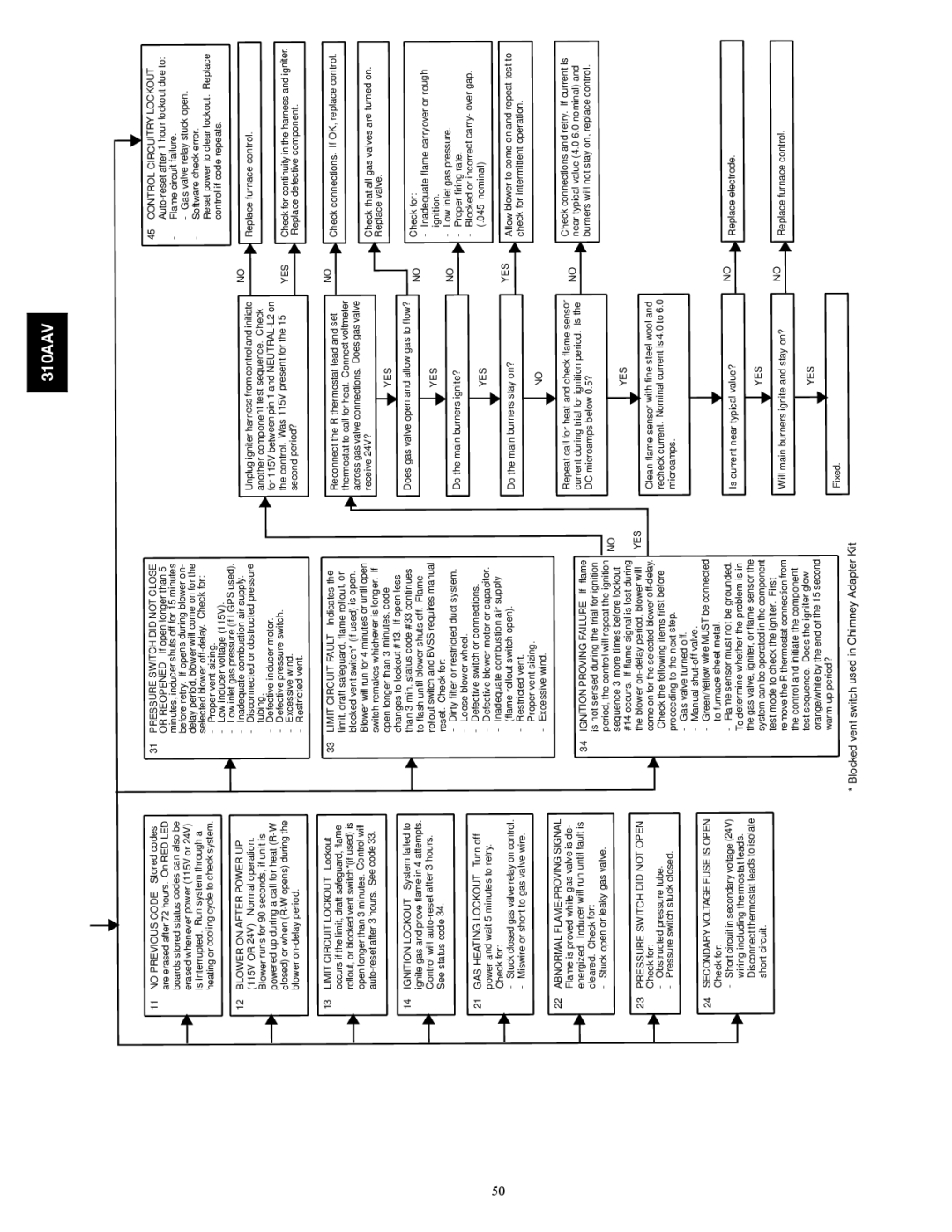
Bryant 310AAV instruction manual Chimneyin KitAdapter VentBlocked usedswitch

310AAV specifications

The Bryant 310AAV and 310JAV are high-efficiency air conditioning and heating systems designed for residential and light commercial applications. These models embody Bryant's commitment to delivering reliable comfort solutions while prioritizing energy efficiency and performance.

One of the standout features of the Bryant 310AAV and 310JAV is their impressive Seasonal Energy Efficiency Ratio (SEER) ratings. The higher the SEER, the more efficient the unit is in using electricity to cool your space. The Bryant 310AAV boasts a SEER rating of up to 16, while the 310JAV offers a slightly lower rating. This efficiency translates into cost savings on monthly energy bills while ensuring indoor comfort throughout the year.

Both models utilize advanced technologies, including two-stage heating and cooling capabilities. This means that the systems can adjust their operation based on the heating or cooling needs of a space, providing optimal temperature control while reducing energy waste. The two-stage operation also contributes to quieter operation levels, making these units suitable for residential settings where noise is a concern.

The 310AAV and 310JAV are equipped with variable-speed compressors, which further enhance their efficiency and comfort levels. The variable-speed technology allows the system to operate at different speeds, ensuring consistent temperature management and reducing the frequency of on-and-off cycling. This leads to steadier indoor temperatures and improved humidity control.

In addition to their performance features, Bryant places a strong emphasis on durability and dependability. The units are constructed with high-quality materials that are designed to withstand various environmental conditions. Features such as a weather-resistant cabinet and an efficient coil design help protect the units from wear and tear, ensuring long-lasting performance.

The implementation of environmentally friendly refrigerant options is another characteristic that demonstrates Bryant's commitment to sustainability. Both the 310AAV and 310JAV utilize R-410A refrigerant, which has a lower environmental impact compared to older refrigerants, aligning with modern standards for eco-friendly HVAC systems.

Overall, the Bryant 310AAV and 310JAV represent a blend of efficiency, advanced technology, and durability. With their attractive SEER ratings, two-stage operation, variable-speed capabilities, and commitment to sustainability, these models stand out as excellent choices for homeowners and businesses looking to enhance their heating and cooling solutions while keeping energy consumption in check. Whether for residential comfort or light commercial use, these Bryant units promise reliability and performance for years to come.