Indoor Air Quality (IAQ) Sensor Input

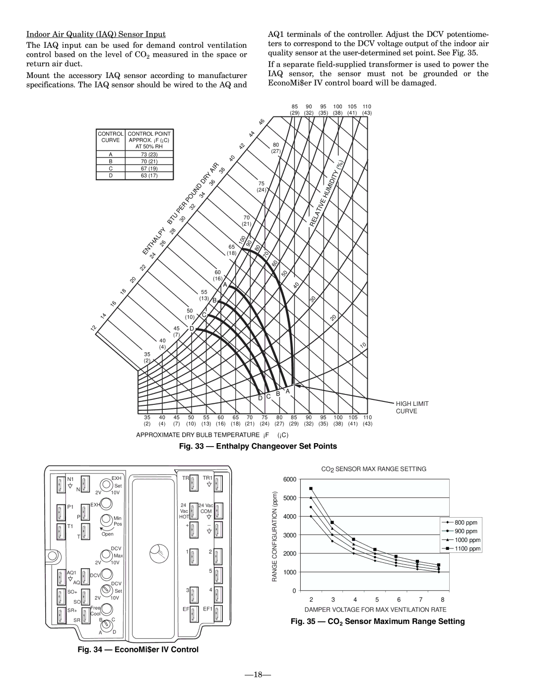
The IAQ input can be used for demand control ventilation control based on the level of CO2 measured in the space or return air duct.

Mount the accessory IAQ sensor according to manufacturer specifications. The IAQ sensor should be wired to the AQ and

AQ1 terminals of the controller. Adjust the DCV potentiome- ters to correspond to the DCV voltage output of the indoor air quality sensor at the user-determined set point. See Fig. 35.

If a separate field-supplied transformer is used to power the IAQ sensor, the sensor must not be grounded or the EconoMi$er IV control board will be damaged.

85

90

95

100

105

110

(29)

(32)

(35)

(38)

(41)

(43)

CONTROL

CURVE

A

B

C

D

1

8


1

6


1

4


1

2


CONTROL POINT

APPROX. °F (°C)

AT 50% RH

73(23)

70(21)

67(19)

63(17)


PO

U

N


R


P

E

32


TU


B


30


P

Y

28


L


HA


26


NT


E

4


2


2

2


2

0


50

(10)

45 D

(7)

40

(4)

35

(2)


IR


40


Y

A

3

8


DR


D


3

6


3

4


65

(18)

60

(16)

A

55

(13)B

C

4

4


42

70

(21)

1

0

0


0


9


46

80

(27)

75

(24)

80

70


60

50

D C B A

4

0


RELA

TIVE


3

0


HUM

IDITY


20

(%

)


0 1

HIGH LIMIT

CURVE

35

40

45

50

55

60

65

70

75

80

85

90

95

100

105

110

(2)

(4)

(7)

(10)

(13)

(16)

(18)

(21)

(24)

(27)

(29)

(32)

(35)

(38)

(41)

(43)

APPROXIMATE DRY BULB TEMPERATURE— °F (°C)

Fig. 33 — Enthalpy Changeover Set Points

N1


EXH

TR

N


Set


2V

10V


P1

EXH


24


Vac


P


Min

HOT

T1


Pos

+


T

Open


DCV

1


Max


2V

10V


AQ1

DCV


AQ


DCV


SO+


Set

3

SO

2V

10V


SR+

Free


EF


Cool


SR

B

C


A

D


TR1

24Vac

COM

_

2

5

4

EF1

CO2 SENSOR MAX RANGE SETTING


6000


(ppm)

5000


CONFIGURATION

4000


800 ppm


3000


900 ppm


1000 ppm


2000


1100 ppm


RANGE

1000


0


2

3

4

5

6

7

8


DAMPER VOLTAGE FOR MAX VENTILATION RATE

Fig. 35 — CO2 Sensor Maximum Range Setting

Fig. 34 — EconoMi$er IV Control

18

Page 18
Image 18
Bryant 551B installation instructions Enthalpy Changeover Set Points

551B specifications

The Bryant 551B and 551C are two highly efficient air conditioning units designed to provide optimal comfort in residential settings. Known for their reliability and performance, these models are part of Bryant's esteemed line of heating and cooling solutions.

One of the standout features of the Bryant 551B is its two-stage cooling system, which allows for better humidity control and increased comfort. This ensures that homeowners can enjoy consistent temperatures while reducing energy consumption. The unit operates quietly, thanks to its noise-reducing technology, making it an ideal choice for bedrooms and living spaces.

On the other hand, the Bryant 551C builds upon this foundation with its variable-speed compressor. This technology allows the unit to adjust its cooling output according to the specific needs of the home. This results in seamless operation and even greater energy efficiency. Both models also incorporate Bryant's advanced control capabilities, which allow users to monitor and adjust settings remotely via smart devices, adding a layer of convenience and modernity to home climate control.

With an emphasis on durability, both the 551B and 551C feature a galvanized steel cabinet that protects against weather-related damage. The powder coat finish further enhances their resistance to rust and corrosion, ensuring a long lifespan and minimal maintenance.

Another significant characteristic of these units is their excellent Seasonal Energy Efficiency Ratio (SEER) ratings. The 551B boasts a SEER rating of up to 16, while the 551C takes it even further with ratings exceeding 20. This efficiency not only translates to lower energy bills for homeowners but also contributes to a reduced carbon footprint, making these units environmentally friendly options.

Both models are also designed to operate with eco-friendly refrigerants, aligning with modern energy standards and regulations aimed at reducing greenhouse gas emissions.

In summary, the Bryant 551B and 551C are exemplary choices for homeowners looking for reliable, efficient, and high-performing air conditioning solutions. With features such as two-stage and variable-speed compressors, advanced smart technology, and robust construction, these models stand out in the competitive HVAC market. They promise a comfortable indoor environment along with significant energy savings, making them a wise investment for the future.