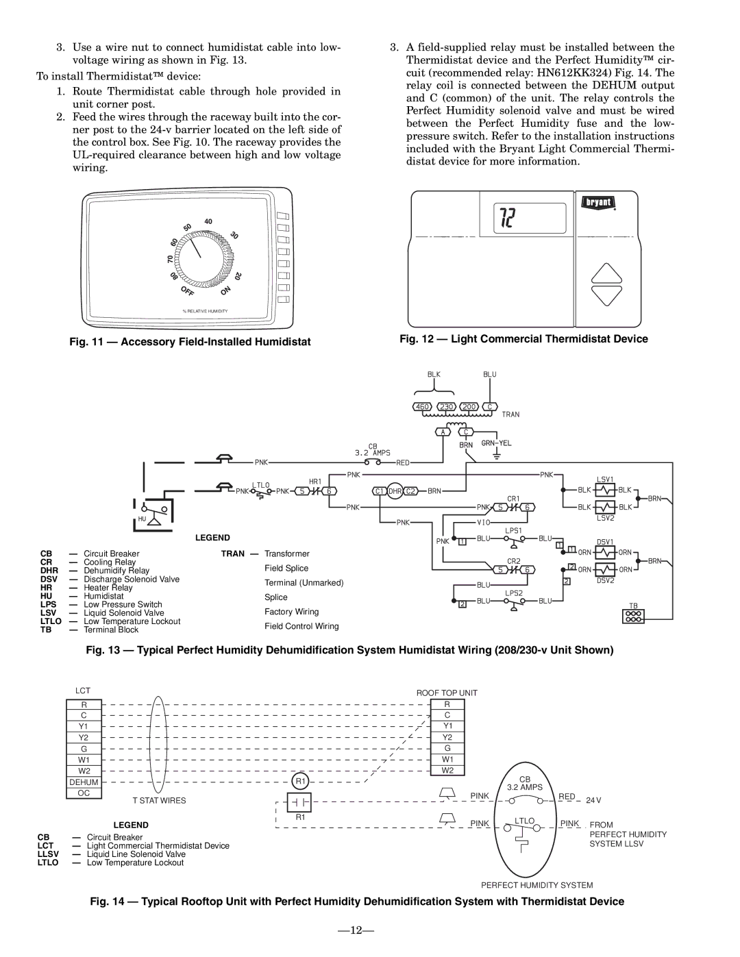
3.Use a wire nut to connect humidistat cable into low- voltage wiring as shown in Fig. 13.

To install Thermidistat™ device:

1.Route Thermidistat cable through hole provided in unit corner post.

2.Feed the wires through the raceway built into the cor- ner post to the 24-v barrier located on the left side of the control box. See Fig. 10. The raceway provides the UL-required clearance between high and low voltage wiring.

3.A field-supplied relay must be installed between the Thermidistat device and the Perfect Humidity™ cir- cuit (recommended relay: HN612KK324) Fig. 14. The relay coil is connected between the DEHUM output and C (common) of the unit. The relay controls the Perfect Humidity solenoid valve and must be wired between the Perfect Humidity fuse and the low- pressure switch. Refer to the installation instructions included with the Bryant Light Commercial Thermi- distat device for more information.

% RELATIVE HUMIDITY

Fig. 11 — Accessory Field-Installed Humidistat


Fig. 12 — Light Commercial Thermidistat Device


LEGEND


CB

Circuit Breaker

TRAN — Transformer


CR

Cooling Relay


Field Splice


DHR

Dehumidify Relay


DSV

Discharge Solenoid Valve


Terminal (Unmarked)


HR

Heater Relay


HU

Humidistat


Splice


LPS

Low Pressure Switch


Factory Wiring


LSV

Liquid Solenoid Valve


LTLO

Low Temperature Lockout


Field Control Wiring


TB

Terminal Block


Fig. 13 — Typical Perfect Humidity Dehumidification System Humidistat Wiring (208/230-v Unit Shown)


LCT


ROOF TOP UNIT


R


R


C


C


Y1


Y1


Y2


Y2


G


G


W1


W1


W2


W2

CB


DEHUM


R1


OC


PINK

3.2 AMPS


RED

24 V


T STAT WIRES


R1

LTLO


LEGEND


PINK

PINK FROM


CB

Circuit Breaker


PERFECT HUMIDITY

LCT

Light Commercial Thermidistat Device


SYSTEM LLSV

LLSV

Liquid Line Solenoid Valve


LTLO

Low Temperature Lockout


PERFECT HUMIDITY SYSTEM

Fig. 14 — Typical Rooftop Unit with Perfect Humidity Dehumidification System with Thermidistat Device

12

Page 12
Image 12
Bryant 551B installation instructions Accessory Field-Installed Humidistat

551B specifications

The Bryant 551B and 551C are two highly efficient air conditioning units designed to provide optimal comfort in residential settings. Known for their reliability and performance, these models are part of Bryant's esteemed line of heating and cooling solutions.

One of the standout features of the Bryant 551B is its two-stage cooling system, which allows for better humidity control and increased comfort. This ensures that homeowners can enjoy consistent temperatures while reducing energy consumption. The unit operates quietly, thanks to its noise-reducing technology, making it an ideal choice for bedrooms and living spaces.

On the other hand, the Bryant 551C builds upon this foundation with its variable-speed compressor. This technology allows the unit to adjust its cooling output according to the specific needs of the home. This results in seamless operation and even greater energy efficiency. Both models also incorporate Bryant's advanced control capabilities, which allow users to monitor and adjust settings remotely via smart devices, adding a layer of convenience and modernity to home climate control.

With an emphasis on durability, both the 551B and 551C feature a galvanized steel cabinet that protects against weather-related damage. The powder coat finish further enhances their resistance to rust and corrosion, ensuring a long lifespan and minimal maintenance.

Another significant characteristic of these units is their excellent Seasonal Energy Efficiency Ratio (SEER) ratings. The 551B boasts a SEER rating of up to 16, while the 551C takes it even further with ratings exceeding 20. This efficiency not only translates to lower energy bills for homeowners but also contributes to a reduced carbon footprint, making these units environmentally friendly options.

Both models are also designed to operate with eco-friendly refrigerants, aligning with modern energy standards and regulations aimed at reducing greenhouse gas emissions.

In summary, the Bryant 551B and 551C are exemplary choices for homeowners looking for reliable, efficient, and high-performing air conditioning solutions. With features such as two-stage and variable-speed compressors, advanced smart technology, and robust construction, these models stand out in the competitive HVAC market. They promise a comfortable indoor environment along with significant energy savings, making them a wise investment for the future.