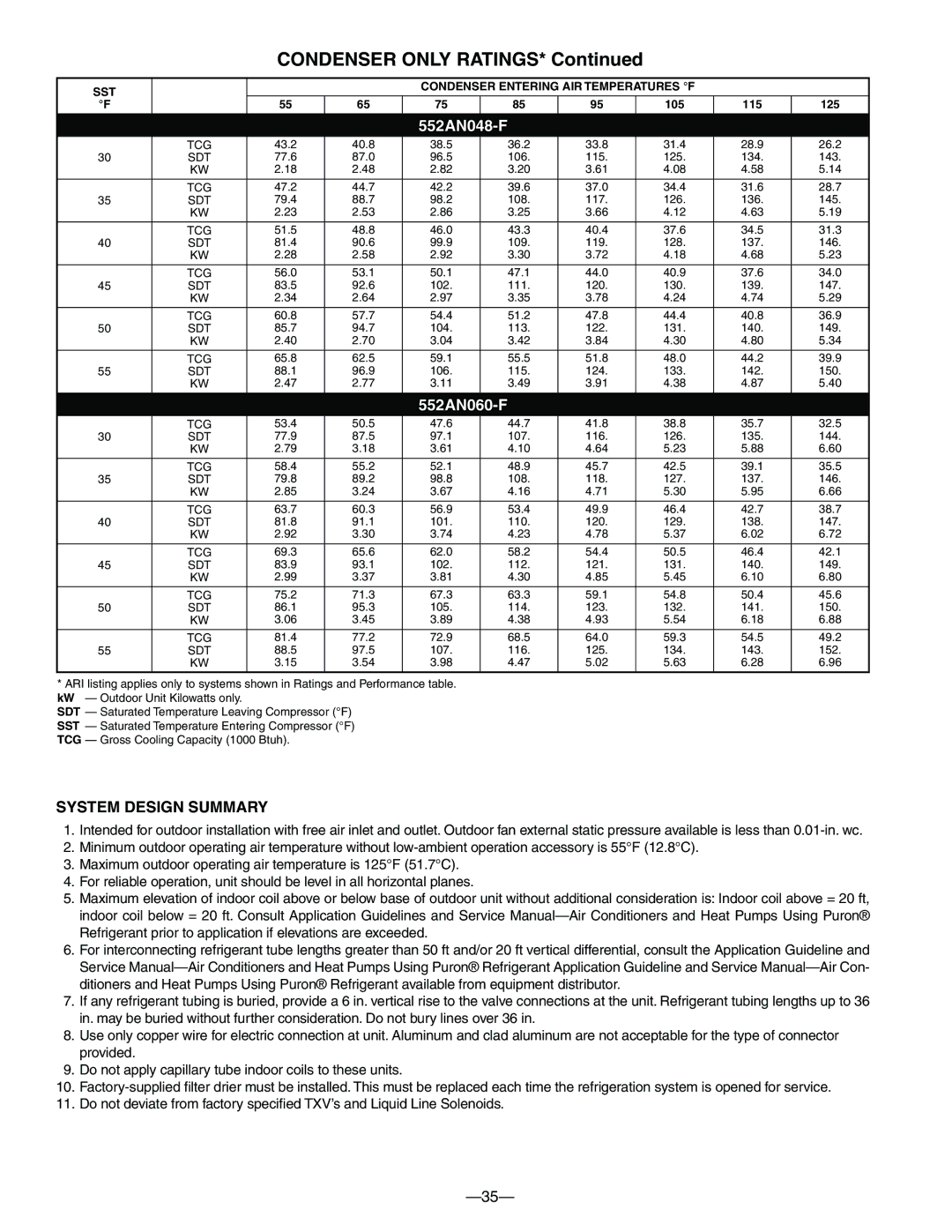
CONDENSER ONLY RATINGS* Continued
SST |
|
|
| CONDENSER ENTERING AIR TEMPERATURES °F |
|
| |||
|
|
|
|
|
|
|
|
| |
°F |
| 55 | 65 | 75 | 85 | 95 | 105 | 115 | 125 |
|
|
|
|
|
|
|
|
|
|
552AN048-F
| TCG | 43.2 | 40.8 | 38.5 | 36.2 | 33.8 | 31.4 | 28.9 | 26.2 |
30 | SDT | 77.6 | 87.0 | 96.5 | 106. | 115. | 125. | 134. | 143. |
| KW | 2.18 | 2.48 | 2.82 | 3.20 | 3.61 | 4.08 | 4.58 | 5.14 |
|
|
|
|
|
|
|
|
|
|
| TCG | 47.2 | 44.7 | 42.2 | 39.6 | 37.0 | 34.4 | 31.6 | 28.7 |
35 | SDT | 79.4 | 88.7 | 98.2 | 108. | 117. | 126. | 136. | 145. |
| KW | 2.23 | 2.53 | 2.86 | 3.25 | 3.66 | 4.12 | 4.63 | 5.19 |
|
|
|
|
|
|
|
|
|
|
| TCG | 51.5 | 48.8 | 46.0 | 43.3 | 40.4 | 37.6 | 34.5 | 31.3 |
40 | SDT | 81.4 | 90.6 | 99.9 | 109. | 119. | 128. | 137. | 146. |
| KW | 2.28 | 2.58 | 2.92 | 3.30 | 3.72 | 4.18 | 4.68 | 5.23 |
|
|
|
|
|
|
|
|
|
|
| TCG | 56.0 | 53.1 | 50.1 | 47.1 | 44.0 | 40.9 | 37.6 | 34.0 |
45 | SDT | 83.5 | 92.6 | 102. | 111. | 120. | 130. | 139. | 147. |
| KW | 2.34 | 2.64 | 2.97 | 3.35 | 3.78 | 4.24 | 4.74 | 5.29 |
|
|
|
|
|
|
|
|
|
|
| TCG | 60.8 | 57.7 | 54.4 | 51.2 | 47.8 | 44.4 | 40.8 | 36.9 |
50 | SDT | 85.7 | 94.7 | 104. | 113. | 122. | 131. | 140. | 149. |
| KW | 2.40 | 2.70 | 3.04 | 3.42 | 3.84 | 4.30 | 4.80 | 5.34 |
|
|
|
|
|
|
|
|
|
|
| TCG | 65.8 | 62.5 | 59.1 | 55.5 | 51.8 | 48.0 | 44.2 | 39.9 |
55 | SDT | 88.1 | 96.9 | 106. | 115. | 124. | 133. | 142. | 150. |
| KW | 2.47 | 2.77 | 3.11 | 3.49 | 3.91 | 4.38 | 4.87 | 5.40 |
|
|
|
|
|
|
|
|
|
|
552AN060-F
| TCG | 53.4 | 50.5 | 47.6 | 44.7 | 41.8 | 38.8 | 35.7 | 32.5 |
30 | SDT | 77.9 | 87.5 | 97.1 | 107. | 116. | 126. | 135. | 144. |
| KW | 2.79 | 3.18 | 3.61 | 4.10 | 4.64 | 5.23 | 5.88 | 6.60 |
|
|
|
|
|
|
|
|
|
|
| TCG | 58.4 | 55.2 | 52.1 | 48.9 | 45.7 | 42.5 | 39.1 | 35.5 |
35 | SDT | 79.8 | 89.2 | 98.8 | 108. | 118. | 127. | 137. | 146. |
| KW | 2.85 | 3.24 | 3.67 | 4.16 | 4.71 | 5.30 | 5.95 | 6.66 |
|
|
|
|
|
|
|
|
|
|
| TCG | 63.7 | 60.3 | 56.9 | 53.4 | 49.9 | 46.4 | 42.7 | 38.7 |
40 | SDT | 81.8 | 91.1 | 101. | 110. | 120. | 129. | 138. | 147. |
| KW | 2.92 | 3.30 | 3.74 | 4.23 | 4.78 | 5.37 | 6.02 | 6.72 |
|
|
|
|
|
|
|
|
|
|
| TCG | 69.3 | 65.6 | 62.0 | 58.2 | 54.4 | 50.5 | 46.4 | 42.1 |
45 | SDT | 83.9 | 93.1 | 102. | 112. | 121. | 131. | 140. | 149. |
| KW | 2.99 | 3.37 | 3.81 | 4.30 | 4.85 | 5.45 | 6.10 | 6.80 |
|
|
|
|
|
|
|
|
|
|
| TCG | 75.2 | 71.3 | 67.3 | 63.3 | 59.1 | 54.8 | 50.4 | 45.6 |
50 | SDT | 86.1 | 95.3 | 105. | 114. | 123. | 132. | 141. | 150. |
| KW | 3.06 | 3.45 | 3.89 | 4.38 | 4.93 | 5.54 | 6.18 | 6.88 |
|
|
|
|
|
|
|
|
|
|
| TCG | 81.4 | 77.2 | 72.9 | 68.5 | 64.0 | 59.3 | 54.5 | 49.2 |
55 | SDT | 88.5 | 97.5 | 107. | 116. | 125. | 134. | 143. | 152. |
| KW | 3.15 | 3.54 | 3.98 | 4.47 | 5.02 | 5.63 | 6.28 | 6.96 |
|
|
|
|
|
|
|
|
|
|
*ARI listing applies only to systems shown in Ratings and Performance table. kW — Outdoor Unit Kilowatts only.
SDT — Saturated Temperature Leaving Compressor (°F) SST — Saturated Temperature Entering Compressor (°F) TCG — Gross Cooling Capacity (1000 Btuh).
SYSTEM DESIGN SUMMARY
1.Intended for outdoor installation with free air inlet and outlet. Outdoor fan external static pressure available is less than
2.Minimum outdoor operating air temperature without
3.Maximum outdoor operating air temperature is 125°F (51.7°C).
4.For reliable operation, unit should be level in all horizontal planes.
5.Maximum elevation of indoor coil above or below base of outdoor unit without additional consideration is: Indoor coil above = 20 ft, indoor coil below = 20 ft. Consult Application Guidelines and Service
6.For interconnecting refrigerant tube lengths greater than 50 ft and/or 20 ft vertical differential, consult the Application Guideline and Service
7.If any refrigerant tubing is buried, provide a 6 in. vertical rise to the valve connections at the unit. Refrigerant tubing lengths up to 36 in. may be buried without further consideration. Do not bury lines over 36 in.
8.Use only copper wire for electric connection at unit. Aluminum and clad aluminum are not acceptable for the type of connector provided.
9.Do not apply capillary tube indoor coils to these units.
10.
11.Do not deviate from factory specified TXV’s and Liquid Line Solenoids.