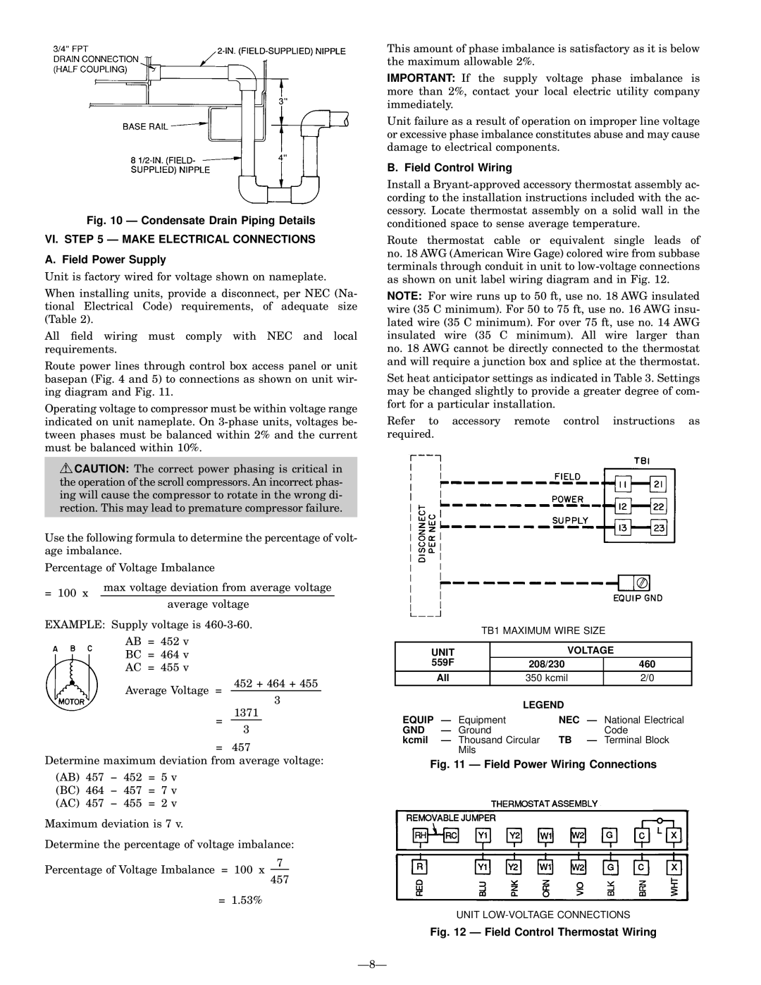
Fig. 10 Ð Condensate Drain Piping Details

VI. STEP 5 Ð MAKE ELECTRICAL CONNECTIONS

A. Field Power Supply

Unit is factory wired for voltage shown on nameplate.

When installing units, provide a disconnect, per NEC (Na- tional Electrical Code) requirements, of adequate size (Table 2).

All ®eld wiring must comply with NEC and local requirements.

Route power lines through control box access panel or unit basepan (Fig. 4 and 5) to connections as shown on unit wir- ing diagram and Fig. 11.

Operating voltage to compressor must be within voltage range indicated on unit nameplate. On 3-phase units, voltages be- tween phases must be balanced within 2% and the current must be balanced within 10%.

CAUTION: The correct power phasing is critical in the operation of the scroll compressors. An incorrect phas- ing will cause the compressor to rotate in the wrong di- rection. This may lead to premature compressor failure.

Use the following formula to determine the percentage of volt- age imbalance.

Percentage of Voltage Imbalance

= 100 x

max voltage deviation from average voltage

average voltage


EXAMPLE: Supply voltage is 460-3-60.

AB = 452 v

BC = 464 v

AC = 455 v

Average Voltage =

452 + 464 + 455

3


=

1371


3

=

457

Determine maximum deviation from average voltage:

(AB) 457 − 452 = 5 v

(BC) 464 − 457 = 7 v

(AC) 457 − 455 = 2 v

Maximum deviation is 7 v.

Determine the percentage of voltage imbalance:

This amount of phase imbalance is satisfactory as it is below the maximum allowable 2%.

IMPORTANT: If the supply voltage phase imbalance is more than 2%, contact your local electric utility company immediately.

Unit failure as a result of operation on improper line voltage or excessive phase imbalance constitutes abuse and may cause damage to electrical components.

B. Field Control Wiring

Install a Bryant-approved accessory thermostat assembly ac- cording to the installation instructions included with the ac- cessory. Locate thermostat assembly on a solid wall in the conditioned space to sense average temperature.

Route thermostat cable or equivalent single leads of no. 18 AWG (American Wire Gage) colored wire from subbase terminals through conduit in unit to low-voltage connections as shown on unit label wiring diagram and in Fig. 12.

NOTE: For wire runs up to 50 ft, use no. 18 AWG insulated wire (35 C minimum). For 50 to 75 ft, use no. 16 AWG insu- lated wire (35 C minimum). For over 75 ft, use no. 14 AWG insulated wire (35 C minimum). All wire larger than no. 18 AWG cannot be directly connected to the thermostat and will require a junction box and splice at the thermostat.

Set heat anticipator settings as indicated in Table 3. Settings may be changed slightly to provide a greater degree of com- fort for a particular installation.

Refer to accessory remote control instructions as required.

TB1 MAXIMUM WIRE SIZE


UNIT


VOLTAGE


559F


208/230


460


All


350 kcmil


2/0


LEGEND


EQUIP Ð Equipment

NEC Ð National Electrical

GND

Ð Ground


Code

kcmil

Ð Thousand Circular TB

Ð Terminal Block


Mils


Fig. 11 Ð Field Power Wiring Connections

Percentage of Voltage Imbalance = 100 x

7

457

= 1.53%

UNIT LOW-VOLTAGE CONNECTIONS

Fig. 12 Ð Field Control Thermostat Wiring

Ð8Ð

Page 8
Image 8
Bryant 559F operation manual VI. Ð Make Electrical Connections, Field Power Supply, Field Control Wiring, Unit Voltage, Gnd

559F specifications

The Bryant 559F is a standout heating and cooling solution, designed with both efficiency and performance in mind. This model is a part of Bryant's legacy of reliability, combining innovative technology with user-friendly features to ensure a comfortable indoor environment throughout the year.

One of the most notable features of the Bryant 559F is its high efficiency rating. With a Seasonal Energy Efficiency Ratio (SEER) that exceeds industry standards, this model is engineered to significantly reduce energy consumption, translating to lower utility bills and a smaller carbon footprint. The system is designed to perform efficiently even in extreme temperatures, making it a reliable choice for households in diverse climates.

Incorporating advanced inverter technology, the Bryant 559F automatically adjusts its output to meet the precise cooling and heating needs of the space, providing consistent comfort while minimizing energy usage. This adaptive capability reduces energy waste, resulting in more efficient operation compared to traditional systems that constantly cycle on and off.

The Bryant 559F also features an integrated Wi-Fi capability, allowing users to control their heating and cooling system remotely via a smartphone app. This modern convenience empowers homeowners to create schedules, adjust settings, and monitor performance from virtually anywhere, enhancing both comfort and energy management.

Another characteristic of the Bryant 559F is its quiet operation. Thanks to sound-dampening features, the system is designed to operate at lower noise levels, providing a peaceful indoor environment. This makes it particularly suitable for residential applications where noise can be a concern, such as bedrooms and home offices.

Additionally, the Bryant 559F is equipped with advanced air filtration and purification systems that help improve indoor air quality. This is particularly beneficial for allergy sufferers or those concerned about pollutants in the air. The system can remove dust, pollen, and other particulates, creating a healthier living space.

Furthermore, the Bryant 559F model is backed by a robust warranty, showcasing Bryant's commitment to quality and customer satisfaction. Overall, the Bryant 559F combines innovative technology, energy efficiency, and user-friendly features to deliver a reliable heating and cooling solution that meets the needs of modern households. Its blend of performance, comfort, and convenience makes it an excellent choice for anyone looking to enhance their indoor climate control solutions.