VIII. STEP 8 Ð INSTALL OUTDOOR-AIR HOOD

The same type of factory-installed hood is used on units with 25% air ventilation and units with an economizer.

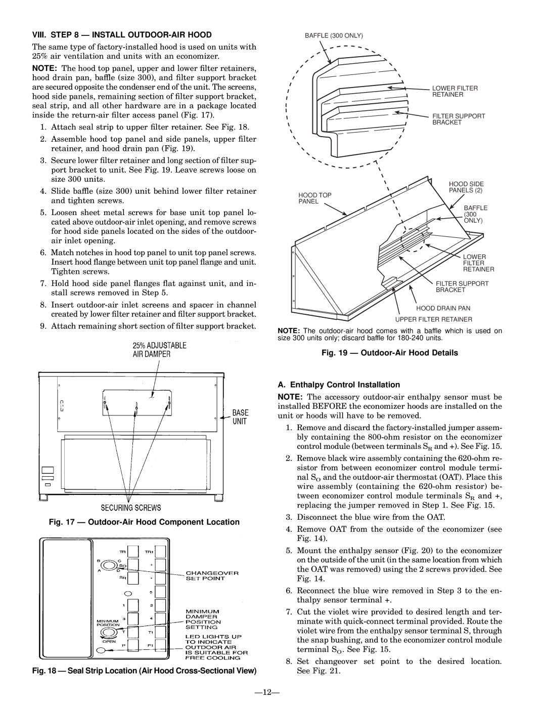
NOTE: The hood top panel, upper and lower ®lter retainers, hood drain pan, baffle (size 300), and ®lter support bracket are secured opposite the condenser end of the unit. The screens, hood side panels, remaining section of ®lter support bracket, seal strip, and all other hardware are in a package located inside the return-air ®lter access panel (Fig. 17).

1.Attach seal strip to upper ®lter retainer. See Fig. 18.

2.Assemble hood top panel and side panels, upper ®lter retainer, and hood drain pan (Fig. 19).

3.Secure lower ®lter retainer and long section of ®lter sup- port bracket to unit. See Fig. 19. Leave screws loose on size 300 units.

4.Slide baffle (size 300) unit behind lower ®lter retainer and tighten screws.

5.Loosen sheet metal screws for base unit top panel lo- cated above outdoor-air inlet opening, and remove screws for hood side panels located on the sides of the outdoor- air inlet opening.

6.Match notches in hood top panel to unit top panel screws. Insert hood ¯ange between unit top panel ¯ange and unit. Tighten screws.

7.Hold hood side panel ¯anges ¯at against unit, and in- stall screws removed in Step 5.

8.Insert outdoor-air inlet screens and spacer in channel created by lower ®lter retainer and ®lter support bracket.

9.Attach remaining short section of ®lter support bracket.

Fig. 17 Ð Outdoor-Air Hood Component Location

Fig. 18 Ð Seal Strip Location (Air Hood Cross-Sectional View)

BAFFLE (300 ONLY)

LOWER FILTER

RETAINER

FILTER SUPPORT

BRACKET

HOOD SIDE

PANELS (2)

HOOD TOP PANEL

BAFFLE (300 ONLY)

LOWER

FILTER

RETAINER

FILTER SUPPORT

BRACKET

HOOD DRAIN PAN

UPPER FILTER RETAINER

NOTE: The outdoor-air hood comes with a baffle which is used on size 300 units only; discard baffle for 180-240 units.

Fig. 19 Ð Outdoor-Air Hood Details

A. Enthalpy Control Installation

NOTE: The accessory outdoor-air enthalpy sensor must be installed BEFORE the economizer hoods are installed on the unit or hoods will have to be removed.

1.Remove and discard the factory-installed jumper assem- bly containing the 800-ohm resistor on the economizer control module (between terminals SR and +). See Fig. 15.

2.Remove black wire assembly containing the 620-ohm re- sistor from between economizer control module termi-

nal SO and the outdoor-air thermostat (OAT). Place this wire assembly (containing the 620-ohm resistor) be-

tween economizer control module terminals SR and +, replacing the jumper removed in Step 1. See Fig. 15.

3.Disconnect the blue wire from the OAT.

4.Remove OAT from the outside of the economizer (see Fig. 14).

5.Mount the enthalpy sensor (Fig. 20) to the economizer on the outside of the unit (in the same location from which the OAT was removed) using the 2 screws provided. See Fig. 14.

6.Reconnect the blue wire removed in Step 3 to the en- thalpy sensor terminal +.

7.Cut the violet wire provided to desired length and ter- minate with quick-connect terminal provided. Route the violet wire from the enthalpy sensor terminal S, through the snap bushing, and to the economizer control module terminal SO. See Fig. 15.

8.Set changeover set point to the desired location. See Fig. 21.

Ð12Ð

Page 12
Image 12
Bryant 559F operation manual VIII. Ð Install OUTDOOR-AIR Hood, Outdoor-Air Hood Component Location

559F specifications

The Bryant 559F is a standout heating and cooling solution, designed with both efficiency and performance in mind. This model is a part of Bryant's legacy of reliability, combining innovative technology with user-friendly features to ensure a comfortable indoor environment throughout the year.

One of the most notable features of the Bryant 559F is its high efficiency rating. With a Seasonal Energy Efficiency Ratio (SEER) that exceeds industry standards, this model is engineered to significantly reduce energy consumption, translating to lower utility bills and a smaller carbon footprint. The system is designed to perform efficiently even in extreme temperatures, making it a reliable choice for households in diverse climates.

Incorporating advanced inverter technology, the Bryant 559F automatically adjusts its output to meet the precise cooling and heating needs of the space, providing consistent comfort while minimizing energy usage. This adaptive capability reduces energy waste, resulting in more efficient operation compared to traditional systems that constantly cycle on and off.

The Bryant 559F also features an integrated Wi-Fi capability, allowing users to control their heating and cooling system remotely via a smartphone app. This modern convenience empowers homeowners to create schedules, adjust settings, and monitor performance from virtually anywhere, enhancing both comfort and energy management.

Another characteristic of the Bryant 559F is its quiet operation. Thanks to sound-dampening features, the system is designed to operate at lower noise levels, providing a peaceful indoor environment. This makes it particularly suitable for residential applications where noise can be a concern, such as bedrooms and home offices.

Additionally, the Bryant 559F is equipped with advanced air filtration and purification systems that help improve indoor air quality. This is particularly beneficial for allergy sufferers or those concerned about pollutants in the air. The system can remove dust, pollen, and other particulates, creating a healthier living space.

Furthermore, the Bryant 559F model is backed by a robust warranty, showcasing Bryant's commitment to quality and customer satisfaction. Overall, the Bryant 559F combines innovative technology, energy efficiency, and user-friendly features to deliver a reliable heating and cooling solution that meets the needs of modern households. Its blend of performance, comfort, and convenience makes it an excellent choice for anyone looking to enhance their indoor climate control solutions.