Bryant 
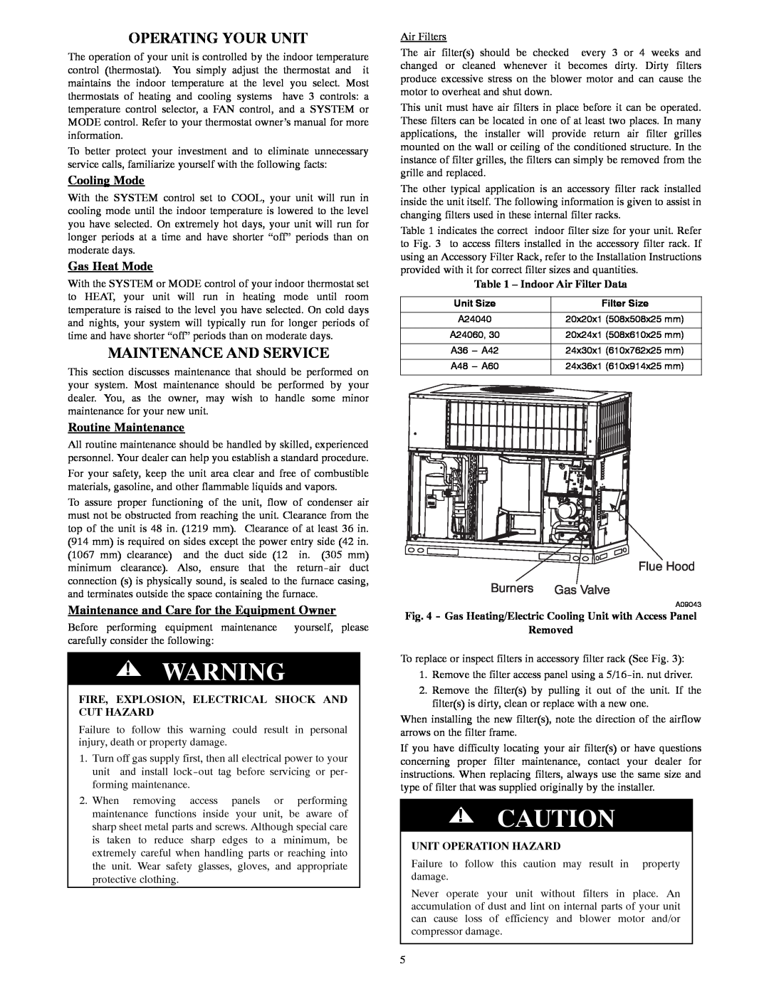
574D Operating Your Unit, Maintenance And Service, Cooling Mode, Gas Heat Mode, Removed

Models: 574D 577C

1 10
Download 10 pages 19.65 Kb
Page 5
Image 5
OPERATING YOUR UNIT

OPERATING YOUR UNIT

The operation of your unit is controlled by the indoor temperature control (thermostat). You simply adjust the thermostat and it maintains the indoor temperature at the level you select. Most thermostats of heating and cooling systems have 3 controls: a temperature control selector, a FAN control, and a SYSTEM or MODE control. Refer to your thermostat owner’s manual for more information.

To better protect your investment and to eliminate unnecessary service calls, familiarize yourself with the following facts:

Cooling Mode

With the SYSTEM control set to COOL, your unit will run in cooling mode until the indoor temperature is lowered to the level you have selected. On extremely hot days, your unit will run for longer periods at a time and have shorter “off” periods than on moderate days.

Gas Heat Mode

With the SYSTEM or MODE control of your indoor thermostat set to HEAT, your unit will run in heating mode until room temperature is raised to the level you have selected. On cold days and nights, your system will typically run for longer periods of time and have shorter “off” periods than on moderate days.

MAINTENANCE AND SERVICE

This section discusses maintenance that should be performed on your system. Most maintenance should be performed by your dealer. You, as the owner, may wish to handle some minor maintenance for your new unit.

Routine Maintenance

All routine maintenance should be handled by skilled, experienced personnel. Your dealer can help you establish a standard procedure.

For your safety, keep the unit area clear and free of combustible materials, gasoline, and other flammable liquids and vapors.

To assure proper functioning of the unit, flow of condenser air must not be obstructed from reaching the unit. Clearance from the top of the unit is 48 in. (1219 mm). Clearance of at least 36 in. (914 mm) is required on sides except the power entry side (42 in. (1067 mm) clearance) and the duct side (12 in. (305 mm) minimum clearance). Also, ensure that the return-air duct connection (s) is physically sound, is sealed to the furnace casing, and terminates outside the space containing the furnace.

Maintenance and Care for the Equipment Owner

Before performing equipment maintenance

yourself, please

carefully consider the following:


!WARNING

FIRE, EXPLOSION, ELECTRICAL SHOCK AND CUT HAZARD

Failure to follow this warning could result in personal injury, death or property damage.

1.Turn off gas supply first, then all electrical power to your unit and install lock-out tag before servicing or per- forming maintenance.

2.When removing access panels or performing maintenance functions inside your unit, be aware of sharp sheet metal parts and screws. Although special care is taken to reduce sharp edges to a minimum, be extremely careful when handling parts or reaching into the unit. Wear safety glasses, gloves, and appropriate protective clothing.

Air Filters

The air filter(s) should be checked every 3 or 4 weeks and changed or cleaned whenever it becomes dirty. Dirty filters produce excessive stress on the blower motor and can cause the motor to overheat and shut down.

This unit must have air filters in place before it can be operated. These filters can be located in one of at least two places. In many applications, the installer will provide return air filter grilles mounted on the wall or ceiling of the conditioned structure. In the instance of filter grilles, the filters can simply be removed from the grille and replaced.

The other typical application is an accessory filter rack installed inside the unit itself. The following information is given to assist in changing filters used in these internal filter racks.

Table 1 indicates the correct indoor filter size for your unit. Refer to Fig. 3 to access filters installed in the accessory filter rack. If using an Accessory Filter Rack, refer to the Installation Instructions provided with it for correct filter sizes and quantities.

Table 1 – Indoor Air Filter Data

Unit Size

Filter Size

A24040

20x20x1 (508x508x25 mm)

A24060, 30

20x24x1 (508x610x25 mm)

A36 --- A42

24x30x1 (610x762x25 mm)

A48 --- A60

24x36x1 (610x914x25 mm)

Flue Hood

Burners Gas Valve

A09043

Fig. 4 - Gas Heating/Electric Cooling Unit with Access Panel

Removed

To replace or inspect filters in accessory filter rack (See Fig. 3):

1.Remove the filter access panel using a 5/16-in. nut driver.

2.Remove the filter(s) by pulling it out of the unit. If the filter(s) is dirty, clean or replace with a new one.

When installing the new filter(s), note the direction of the airflow arrows on the filter frame.

If you have difficulty locating your air filter(s) or have questions concerning proper filter maintenance, contact your dealer for instructions. When replacing filters, always use the same size and type of filter that was supplied originally by the installer.

!CAUTION

UNIT OPERATION HAZARD

Failure to follow this caution may result in property damage.

Never operate your unit without filters in place. An accumulation of dust and lint on internal parts of your unit can cause loss of efficiency and blower motor and/or compressor damage.

5

Page 5
Image 5
Bryant 574D, 577C Operating Your Unit, Maintenance And Service, Cooling Mode, Gas Heat Mode, Routine Maintenance, Removed