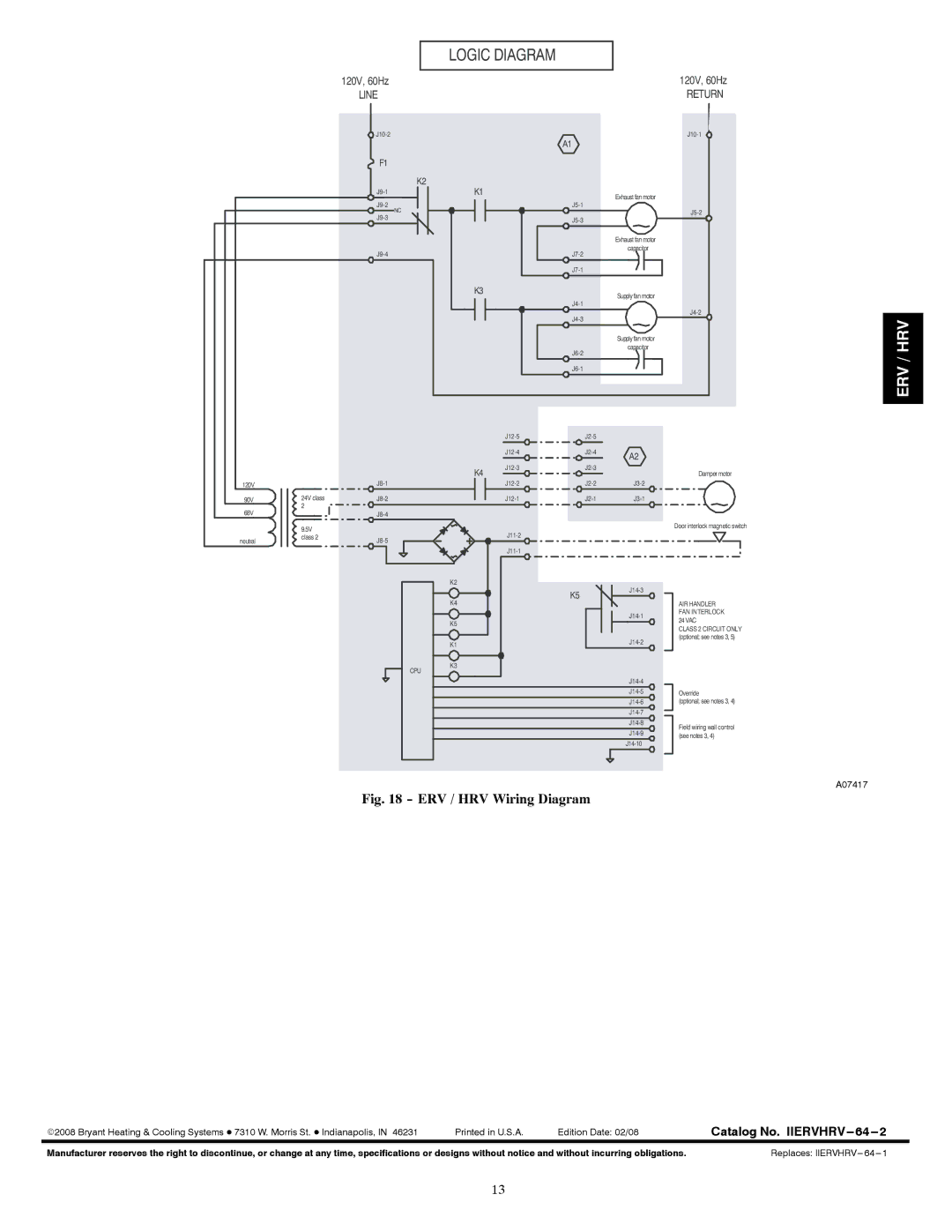
LOGIC DIAGRAM
|
| 120V, 60Hz |
|
|
|
| 120V, 60Hz |
|
| LINE |
|
|
|
| RETURN |
|
|
|
| A1 |
| ||
|
|
|
|
|
|
| |
|
| F1 |
|
|
|
|
|
|
|
| K2 |
|
|
|
|
|
| K1 |
|
| Exhaust fan motor |
| |
|
|
|
|
| |||
|
| NC |
|
| |||
|
|
|
|
|
| ||
|
|
|
|
| |||
|
|
|
|
|
| ||
|
|
|
|
|
|
| |
|
|
|
|
|
| Exhaust fan motor |
|
|
|
|
| capacitor |
| ||
|
|
|
|
|
| ||
|
|
|
|
|
|
| |
|
|
| K3 |
|
| Supply fan motor |
|
|
|
|
|
|
| ||
|
|
|
|
|
|
| |
|
|
|
|
|
| ||
|
|
|
|
|
|
| |
|
|
|
|
|
| Supply fan motor |
|
|
|
|
|
| capacitor |
| |
|
|
|
|
|
|
| |
|
|
|
|
|
|
| |
|
|
|
|
|
| ||
|
|
|
| A2 |
| ||
|
|
|
|
|
|
| |
|
|
| K4 |
| Damper motor | ||
|
|
|
|
|
| ||
120V |
|
|
| ||||
90V | 24V class |
|
| ||||
68V | 2 |
|
|
|
|
|
|
|
|
|
|
|
| ||
| 9.5V |
|
|
|
|
| Door interlock magnetic switch |
|
|
|
|
|
| ||
neutral | class 2 |
|
|
|
| ||
|
|
|
|
|
| ||
|
|
|
|
|
|
| |
|
|
| K2 |
|
|
| |
|
|
|
|
| K5 |
| |
|
|
| K4 |
|
| AIR HANDLER | |
|
|
|
|
|
| ||
|
|
|
|
|
| FAN INTERLOCK | |
|
|
| K5 |
|
| 24 VAC | |
|
|
|
|
|
| ||
|
|
|
|
|
|
|
CLASS 2 CIRCUIT ONLY (optional; see notes 3, 5)
K1 |
K3
CPU
|
|
|
|
|
| ||
|
|
|
|
| Override | ||
|
|
|
|
| (optional; see notes 3, 4) | ||
|
|
|
|
|
|
| |
|
|
|
|
|
| ||
|
|
|
|
|
| Field wiring wall control | |
|
|
|
|
| |||
|
|
|
|
| (see notes 3, 4) | ||
|
|
|
|
|
|
| |
A07417
Fig. 18 - ERV / HRV Wiring Diagram
ERV / HRV
E2008 Bryant Heating & Cooling Systems D 7310 W. Morris St. D Indianapolis, IN 46231 | Printed in U.S.A. | Edition Date: 02/08 | Catalog No. | 2 |
Manufacturer reserves the right to discontinue, or change at any time, specifications or designs without notice and without incurring obligations. | Replaces: | 1 | ||
13