|
| THERMOSTAT |
|
|
| TYPICAL | |||||||
|
|
|
| B |
|
|
| UNIT |
| ||||
|
|
|
| O |
|
|
|
|
|
| |||
| W2 Y2 R W1 Y1 G | C |
|
|
| ||||||||
|
|
|
|
|
|
|
|
|
|
|
|
| L |
|
|
|
|
|
|
|
|
|
|
|
|
| E |
|
|
|
|
|
|
|
|
|
|
|
|
| |
|
|
|
|
|
|
|
|
|
| 24 VAC COMMON |
| C | |
|
|
|
|
|
|
|
|
|
| FAN RELAY |
| ||
|
|
|
|
|
|
|
|
|
| G | |||
|
|
|
|
|
|
|
|
|
| COMPRESSOR RELAY | |||
|
|
|
|
|
|
|
|
|
| Y1 | |||
|
|
|
|
|
|
|
|
|
|
|
|
| |
|
|
|
|
|
|
|
|
|
| 1st STAGE HEAT CIRCUIT |
| O | |
|
|
|
|
|
|
|
|
|
| W1 | |||
|
|
|
|
|
|
|
|
|
| 24 VAC RETURN | |||
|
|
|
|
|
|
|
|
|
| R | |||
|
|
|
|
|
|
|
|
|
|
|
|
| |
|
|
|
|
|
|
|
|
|
| 2nd STAGE HEAT CIRCUIT | Y2 | ||
|
|
|
|
|
|
|
|
|
| W2 | |||
|
|
|
|
|
|
|
|
|
|
|
|
| |
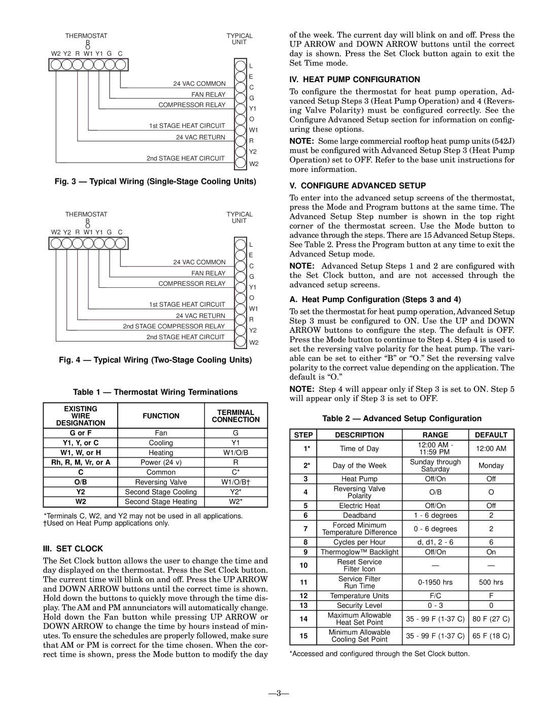
| Fig. 3 Ð Typical Wiring | ||||||||||||
|
| THERMOSTAT |
|
|
| TYPICAL | |||||||
|
|
|
| B |
|
|
| UNIT |
| ||||
|
|
|
| O |
|
|
|
|
|
| |||
| W2 Y2 R W1 Y1 G | C |
|
|
| ||||||||
|
|
|
|
|
|
|
|
|
|
|
|
| L |
|
|
|
|
|
|
|
|
|
|
|
|
| E |
|
|
|
|
|
|
|
|
|
| 24 VAC COMMON |
| C | |
|
|
|
|
|
|
|
|
|
| FAN RELAY |
| ||
|
|
|
|
|
|
|
|
|
| G | |||
|
|
|
|
|
|
|
|
|
| COMPRESSOR RELAY | |||
|
|
|
|
|
|
|
|
|
| Y1 | |||
|
|
|
|
|
|
|
|
|
|
|
|
| |
|
|
|
|
|
|
|
|
|
| 1st STAGE HEAT CIRCUIT |
| O | |
|
|
|
|
|
|
|
|
|
| W1 | |||
|
|
|
|
|
|
|
|
|
| 24 VAC RETURN |
| ||
|
|
|
|
|
|
|
|
|
| R | |||
|
|
|
|
|
|
|
|
| 2nd STAGE COMPRESSOR RELAY |
| |||
|
|
|
|
|
|
|
|
| Y2 | ||||
|
|
|
|
|
|
|
|
|
| 2nd STAGE HEAT CIRCUIT | |||
|
|
|
|
|
|
|
|
|
| W2 | |||
|
|
|
|
|
|
|
|
|
|
|
|
| |
| Fig. 4 Ð Typical Wiring | ||||||||||||
|
|
| Table 1 Ð Thermostat Wiring Terminations |
| |||||||||
|
|
|
|
|
|
|
|
|
|
|
|
|
|
|
| EXISTING |
|
|
| TERMINAL | |||||||
|
|
| WIRE |
|
| FUNCTION | |||||||
|
|
|
|
| CONNECTION | ||||||||
| DESIGNATION |
|
|
| |||||||||
|
|
|
|
|
|
| |||||||
|
|
| G or F |
|
| Fan | G |
| |||||
|
| Y1, Y, or C |
|
| Cooling | Y1 |
| ||||||
|
| W1, W, or H |
|
| Heating | W1/O/B |
| ||||||
| Rh, R, M, Vr, or A |
|
| Power (24 v) | R |
| |||||||
|
|
| C |
|
| Common | C* |
| |||||
|
|
| O/B |
|
| Reversing Valve | W1/O/B² |
| |||||
|
|
| Y2 |
| Second Stage Cooling | Y2* |
| ||||||
|
|
| W2 |
| Second Stage Heating | W2* |
| ||||||
|
|
|
|
|
|
|
|
|
|
|
|
|
|
*Terminals C, W2, and Y2 may not be used in all applications. ²Used on Heat Pump applications only.
III. SET CLOCK
The Set Clock button allows the user to change the time and day displayed on the thermostat. Press the Set Clock button. The current time will blink on and off. Press the UP ARROW and DOWN ARROW buttons until the correct time is shown. Hold down the buttons to quickly move through the time dis- play. The AM and PM annunciators will automatically change. Hold down the Fan button while pressing UP ARROW or DOWN ARROW to change the time by hours instead of min- utes. To ensure the schedules are properly followed, make sure that AM or PM is correct for the time chosen. When the cor- rect time is shown, press the Mode button to modify the day
of the week. The current day will blink on and off. Press the UP ARROW and DOWN ARROW buttons until the correct day is shown. Press the Set Clock button again to exit the Set Time mode.
IV. HEAT PUMP CONFIGURATION
To con®gure the thermostat for heat pump operation, Ad- vanced Setup Steps 3 (Heat Pump Operation) and 4 (Revers- ing Valve Polarity) must be con®gured correctly. See the Con®gure Advanced Setup section for information on con®g- uring these options.
NOTE: Some large commercial rooftop heat pump units (542J) must be con®gured with Advanced Setup Step 3 (Heat Pump Operation) set to OFF. Refer to the base unit instructions for more information.
V. CONFIGURE ADVANCED SETUP
To enter into the advanced setup screens of the thermostat, press the Mode and Program buttons at the same time. The Advanced Setup Step number is shown in the top right corner of the thermostat screen. Use the Mode button to advance through the steps. There are 15 Advanced Setup Steps. See Table 2. Press the Program button at any time to exit the Advanced Setup mode.
NOTE: Advanced Setup Steps 1 and 2 are con®gured with the Set Clock button, and are not accessed through the advanced setup screens.
A. Heat Pump Con®guration (Steps 3 and 4)
To set the thermostat for heat pump operation, Advanced Setup Step 3 must be con®gured to ON. Use the UP and DOWN ARROW buttons to con®gure the step. The default is OFF. Press the Mode button to continue to Step 4. Step 4 is used to set the reversing valve polarity for the heat pump. The vari- able can be set to either ``B'' or ``O.'' Set the reversing valve polarity to the correct value depending on the application. The default is ``O.''
NOTE: Step 4 will appear only if Step 3 is set to ON. Step 5 will appear only if Step 3 is set to OFF.
Table 2 Ð Advanced Setup Con®guration
STEP | DESCRIPTION | RANGE | DEFAULT | |
1* | Time of Day | 12:00 AM - | 12:00 AM | |
11:59 PM | ||||
|
|
| ||
2* | Day of the Week | Sunday through | Monday | |
Saturday | ||||
|
|
| ||
3 | Heat Pump | Off/On | Off | |
4 | Reversing Valve | O/B | O | |
Polarity | ||||
|
|
| ||
5 | Electric Heat | Off/On | Off | |
6 | Deadband | 1 - 6 degrees | 2 | |
7 | Forced Minimum | 0 - 6 degrees | 2 | |
Temperature Difference | ||||
|
|
| ||
8 | Cycles per Hour | d, d1, 2 - 6 | 6 | |
9 | Thermoglow™ Backlight | Off/On | On | |
10 | Reset Service | Ð | Ð | |
Filter Icon | ||||
|
|
| ||
11 | Service Filter | 500 hrs | ||
Run Time | ||||
|
|
| ||
12 | Temperature Units | F/C | F | |
13 | Security Level | 0 - 3 | 0 | |
14 | Maximum Allowable | 35 - 99 F | 80 F (27 C) | |
Heat Set Point | ||||
|
|
| ||
15 | Minimum Allowable | 35 - 99 F | 65 F (18 C) | |
Cooling Set Point | ||||
|
|
|
*Accessed and con®gured through the Set Clock button.
Ð3Ð