Manuals
/
Bryston
/
Home Audio
/
Stereo Amplifier
Bryston
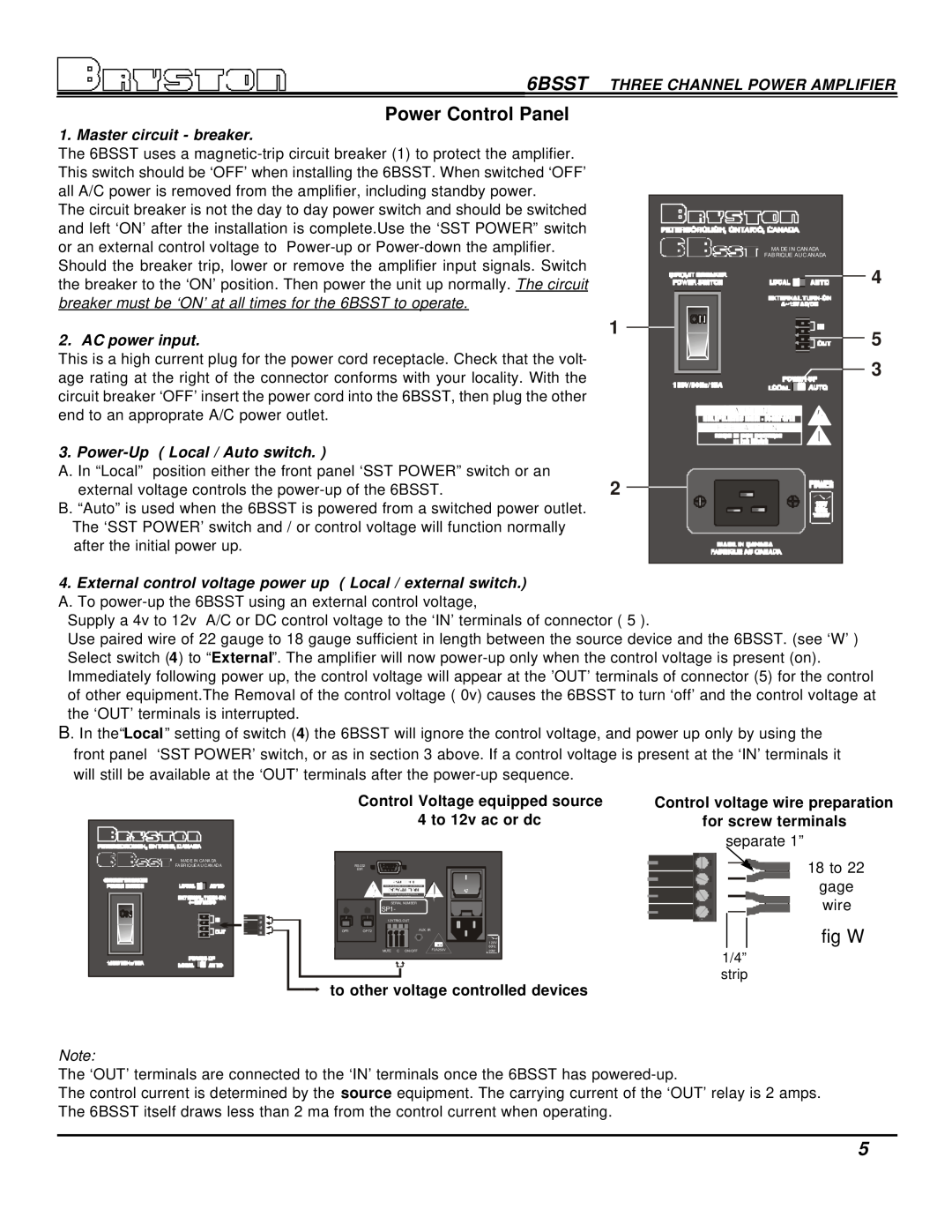
6BSST Power Control Panel, fig W, Control Voltage equipped source, 4 to 12v ac or dc
Models:
6BSST
1
7
16
16
Download
16 pages
29.29 Kb
4
5
6
7
8
9
10
11
Specs
LED Indicators
Warranty
Typical 5.1 Home Theatre Setup
Typical Phase Response
A/C power
Page 7
Image 7
Page 6
Page 8
Page 7
Image 7
Page 6
Page 8
Contents
Model 6BSST
Instructions For Bryston SST Series Amplifiers
5.1 Typical Home Theatre Setup
Table of Contents
Rear Panel Input Settings/Connections
Power Control Panel
Introduction
Warranty see back page for details
Wiring the 6BSST also see rear panel description
A/C power
Rear Panel Input / Output Connections
6. Output binding posts & polarity
6BSST THREE CHANNEL POWER AMPLIFIER
7. Rear Handle Page 2 Fig
2. LED Indicators
Front Panel
6BSST THREE CHANNEL POWER AMPLIFIER
1. SST POWER switch
4 to 12v ac or dc
Power Control Panel
fig W
Control Voltage equipped source
REMOVE 3-32SCREWS FROM THIS SIDE
Rack Mounting Instructions
REMOVE 6-32SCREWS FROM THIS SIDE
DO NOT REMOVE
Left Front
Typical 5.1 Home Theatre Setup
Powered Subwoofer
PRECAUTION
6BSST THREE CHANNEL POWER AMPLIFIER
balanced input with 23dB gain shown
Typical THD+N Harmonic Content
Power supply artifacts are all below -95dBu
Typical Band-passNoise
4 ohm 600w 8 ohm 300w
Typical Phase Response
Typical Frequency Response
8 ohm 300w .01dB 20Khz 4 ohm 500w .1dB 20Khz
4 ohm 600w 8 ohm 300w
Typical THD+N Sweep
Typical IMD Sweep
4v balanced input shown
channel 2 reading with channels 1 & 3 driven to
Damping Factor
Typical Crosstalk
8 ohm reference
Weight
Technical Specifications
CHECK OUR WEB SITE AT www@bryston.ca
BRYSTON 20 -YEARWARRANTY
BRYSTON SERVICE U.S.A. 70 COVENTRY ST SUITE #5
NEWPORT VERMONT. U.S.A. PHONE: 802- 334-1201FAX:
Top
Page
Image
Contents