On 551J units equipped with
The Fire Shutdown Switch configuration, MENU→Config→Inputs→input 5, identifies the normally open status of this input when there is no fire alarm.
Connecting Discrete Inputs
551J |
|
| Filter Status |
|
|
|
|
|
j | The filter status accessory is a | |||||||
This accessory | detects | plugged | filters. When | installing | ||||
|
|
| this accessory, the unit must be configured for filter status | |||||
|
|
| by setting MENU→Config→Inputs→input 3, 5, 8, or 9 | |||||
|
|
| to Filter Status and normally open (N/O) or normally | |||||
|
|
| closed (N/C). Input 8 or 9 is recommended for easy of | |||||
|
|
| installation. Refer to Fig. 36 and Fig. 38 for wire | |||||
|
|
| terminations at J5. |
|
|
|
| |
|
|
| Fan Status |
|
|
|
|
|
|
|
| The fan status accessory is a | |||||
|
|
| This accessory detects when the indoor fan is blowing air. | |||||
|
|
| When installing this accessory, the unit must be | |||||
|
|
| configured | for | fan | status | by | setting |
MENU→Config→Inputs→input 3, 5, 8, or 9 to Fan Status and normally open (N/O) or normally closed (N/C). Input 8 or 9 is recommended for easy of installation. Refer to Fig. 36 and Fig. 38 for wire terminations at J5.
Remote Occupancy
The remote occupancy accessory is a
Also set MENU→Schedules→occupancy source to DI on/off. Input 8 or 9 is recommended for easy of installation. Refer to Fig. 36 and Table 3 for wire terminations at J5.
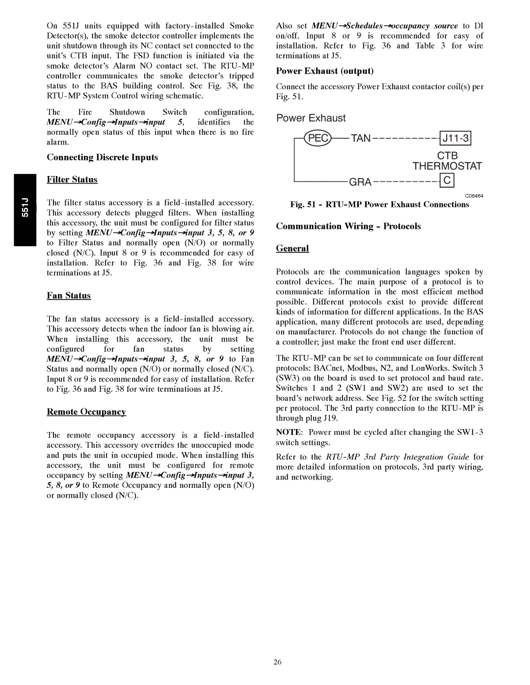
Power Exhaust (output)
Connect the accessory Power Exhaust contactor coil(s) per Fig. 51.
Power Exhaust |
|
|
|
|
| |
|
|
|
|
|
|
|
| PEC |
| TAN |
|
| |
|
|
|
| |||
|
|
|
| CTB | ||
|
|
|
| THERMOSTAT | ||
|
| GRA |
| C | ||
|
|
| ||||
|
|
|
|
| C08464 | |
Fig. 51 - RTU-MP Power Exhaust Connections
Communication Wiring - Protocols
General
Protocols are the communication languages spoken by control devices. The main purpose of a protocol is to communicate information in the most efficient method possible. Different protocols exist to provide different kinds of information for different applications. In the BAS application, many different protocols are used, depending on manufacturer. Protocols do not change the function of a controller; just make the front end user different.
The
NOTE: Power must be cycled after changing the
Refer to the
26