DISCONNECT | EMT OR RIGID CONDUIT | SINGLE | CENTER | MANUAL RESET |
MOUNTING | POINT BOX | POST | LIMIT SWITCH | |
LOCATION |
|
|
| HEATER |
|
|
|
| |
|
|
|
| COVERS |
|
| SINGLE POINT |
|
|
|
MAIN | BRACKET AND | BOX | HEATER | HEATER | HEATER |
CONTROL CONDUIT | MOUNTING | MODULE | MODULE | MOUNTING | |
BOX | DRIP BOOT | SCREW | (LOCATION 1) (LOCATION 2) BRACKET | ||
CONTROL WIRE TERMINAL BLOCK
C08134
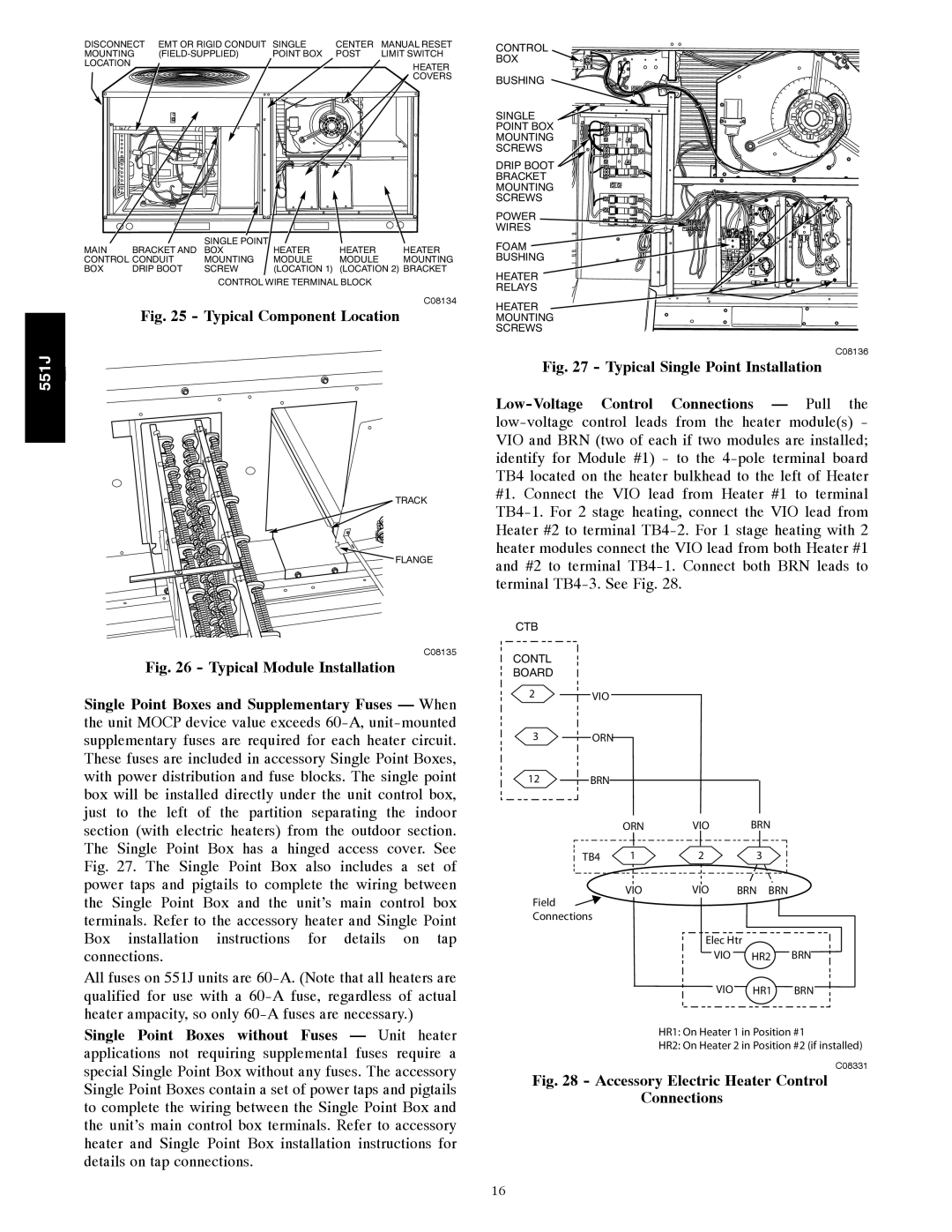
Fig. 25 - Typical Component Location
551J | j |
|
TRACK
FLANGE
C08135
Fig. 26 - Typical Module Installation
Single Point Boxes and Supplementary Fuses — When the unit MOCP device value exceeds 60-A, unit-mounted supplementary fuses are required for each heater circuit. These fuses are included in accessory Single Point Boxes, with power distribution and fuse blocks. The single point box will be installed directly under the unit control box, just to the left of the partition separating the indoor section (with electric heaters) from the outdoor section. The Single Point Box has a hinged access cover. See Fig. 27. The Single Point Box also includes a set of power taps and pigtails to complete the wiring between the Single Point Box and the unit’s main control box terminals. Refer to the accessory heater and Single Point Box installation instructions for details on tap connections.
All fuses on 551J units are
Single Point Boxes without Fuses — Unit heater applications not requiring supplemental fuses require a special Single Point Box without any fuses. The accessory Single Point Boxes contain a set of power taps and pigtails to complete the wiring between the Single Point Box and the unit’s main control box terminals. Refer to accessory heater and Single Point Box installation instructions for details on tap connections.
CONTROL |
BOX |
BUSHING |
|
SINGLE |
|
POINT BOX |
|
MOUNTING |
|
SCREWS |
|
DRIP BOOT |
|
BRACKET |
|
MOUNTING |
|
SCREWS |
|
POWER |
|
WIRES |
|
FOAM |
|
BUSHING |
|
| 22.2 |
23 | 1 |
3 |
HEATER
RELAYS
HEATER
MOUNTING
SCREWS
C08136
Fig. 27 - Typical Single Point Installation
Low-Voltage Control Connections — Pull the low-voltage control leads from the heater module(s) - VIO and BRN (two of each if two modules are installed; identify for Module #1) - to the 4-pole terminal board TB4 located on the heater bulkhead to the left of Heater #1. Connect the VIO lead from Heater #1 to terminal TB4-1. For 2 stage heating, connect the VIO lead from Heater #2 to terminal TB4-2. For 1 stage heating with 2 heater modules connect the VIO lead from both Heater #1 and #2 to terminal TB4-1. Connect both BRN leads to terminal TB4-3. See Fig. 28.
CTB
CONTL
BOARD
2VIO
3ORN
12 BRN
| ORN | VIO | BRN |
TB4 | 1 | 2 | 3 |
| VIO | VIO | BRN BRN |
Field
Connections
Elec Htr
VIO HR2 BRN
VIO HR1 | BRN |
HR1: On Heater 1 in Position #1
HR2: On Heater 2 in Position #2 (if installed)
C08331
Fig. 28 - Accessory Electric Heater Control
Connections
16