Outdoor Air Temperature (OAT) Sensor - The OAT is
EconoMi$er2 - The
Outdoor air management functions can be enhanced with
Enthalpy control (outdoor air or differential sensors) Space CO2 sensor
Outdoor air CO2 sensor
Field Connections - Field connections for accessory sensors and input devices are made the
Space Temperature (SPT) Sensors
A
S 33ZCT55SPT, space temperature sensor with override button
S 33ZCT56SPT, space temperature sensor with override button and setpoint adjustment
S 33ZCT59SPT, space temperature sensor with LCD (liquid crystal display) screen, override button, and setpoint adjustment
Use 20 gauge wire to connect the sensor to the controller. The wire is suitable for distances of up to 500 ft. Use a
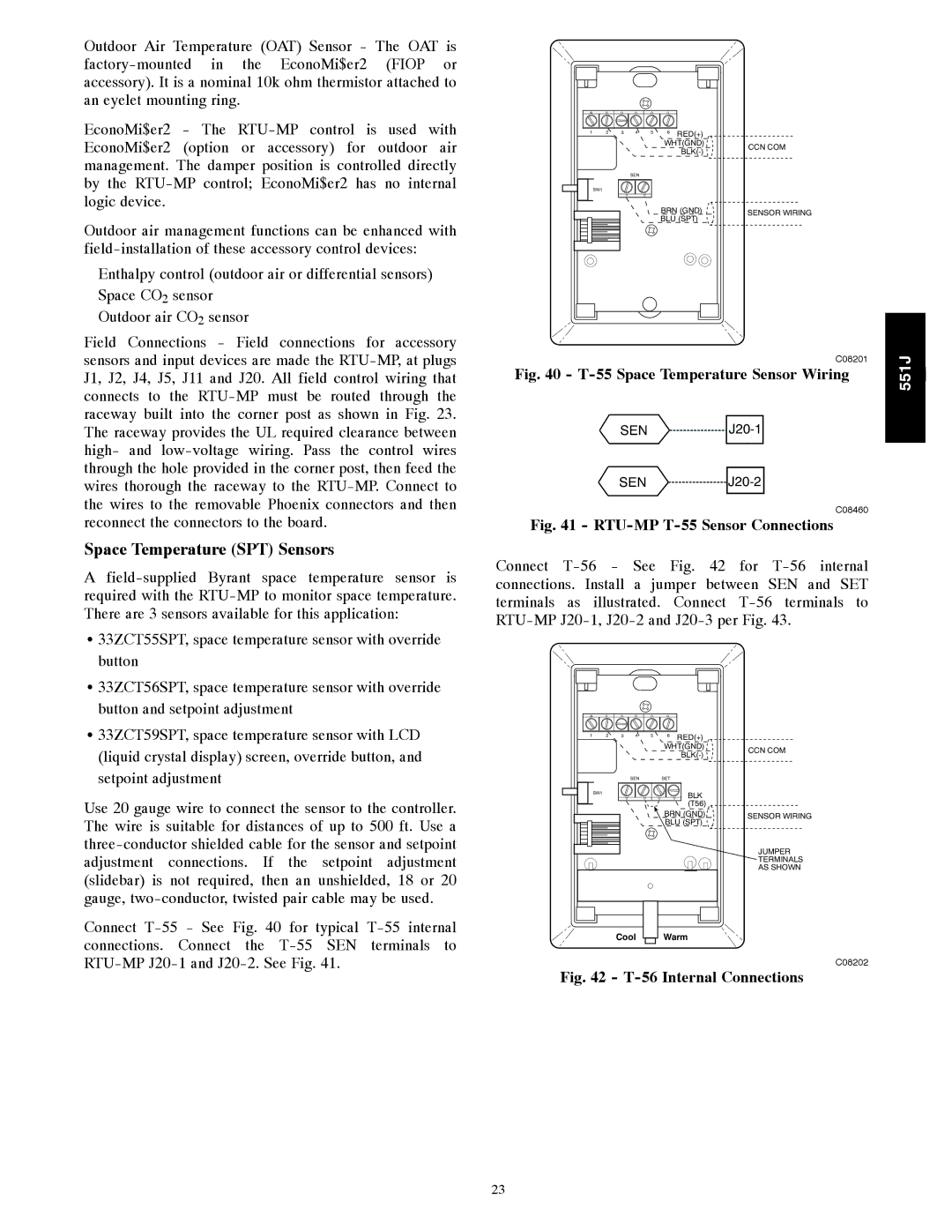
Connect
1 | 2 | 3 | 4 | 5 | 6 | RED(+) |
|
|
|
|
|
| WHT(GND) | CCN COM | |
|
|
|
|
|
| ||
|
|
|
|
|
|
| |
|
|
| SEN |
|
|
|
|
| SW1 |
|
|
|
|
|
|
|
|
|
|
| BRN (GND) | SENSOR WIRING | |
|
|
|
|
| BLU (SPT) |
| |
C08201 | 551J | j | |
Fig. 40 - | |||
|
SEN ![]()
![]()
SEN ![]()
![]() J20-2
J20-2
C08460
Fig. 41 - RTU-MP T-55 Sensor Connections
Connect
1 | 2 | 3 | 4 | 5 | 6 | RED(+) |
|
|
|
|
|
| WHT(GND) | CCN COM | |
|
|
|
|
|
| ||
|
|
|
|
|
|
| |
|
|
| SEN |
| SET |
|
|
| SW1 |
|
|
|
| BLK |
|
|
|
|
|
|
|
| |
|
|
|
|
|
| (T56) |
|
|
|
|
|
| BRN (GND) | SENSOR WIRING | |
|
|
|
|
| BLU (SPT) |
| |
|
|
|
|
|
|
| JUMPER |
|
|
|
|
|
|
| TERMINALS |
|
|
|
|
|
|
| AS SHOWN |
Cool Warm
C08202
Fig. 42 - T-56 Internal Connections
23