Positioning on Curb —
Position unit on roof curb so that the following clearances are maintained: 1/4 in. (6.4 mm) clearance between the roof curb and the base rail inside the front and rear, 0.0 in. clearance between the roof curb and the base rail inside on the duct end of the unit. This will result in the distance between the roof curb and the base rail inside on the condenser end of the unit being approximately equal to Fig. 3, section
Although unit is weatherproof, guard against water from higher level runoff and overhangs.
!CAUTION
UNIT DAMAGE HAZARD
Failure to follow this caution may result in equipment damage.
All panels must be in place when rigging. Unit is not designed for handling by fork truck.
After unit is in position, remove rigging skids and shipping materials.
Step 7 — Convert to Horizontal and Connect Ductwork (when required)
Unit is shipped in the vertical duct configuration. Unit without
C06108
Fig. 6 - Horizontal Conversion Panels
Do not cover or obscure visibility to the unit’s informative data plate when insulating horizontal ductwork.
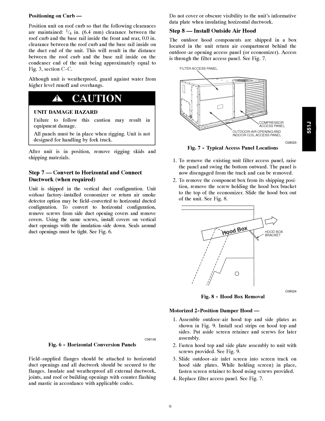
Step 8 — Install Outside Air Hood
The outdoor hood components are shipped in a box located in the unit return air compartment behind the
FILTER ACCESS PANEL
COMPRESSOR | 551J | j |
ACCESS PANEL |
|
|
INDOOR COIL ACCESS PANEL |
|
|
| C06023 |
|
Fig. 7 - Typical Access Panel Locations
1.To remove the existing unit filter access panel, raise the panel and swing the bottom outward. The panel is now disengaged from the track and can be removed.
2.To remove the component box from its shipping posi- tion, remove the screw holding the hood box bracket to the top of the economizer. Slide the hood box out of the unit. See Fig. 8.
|
|
| x |
|
|
| o |
| |
o | B |
| HOOD BOX | |
H | od |
|
| |
|
|
| BRACKET | |
|
|
|
| |
C06024
Fig. 8 - Hood Box Removal
Motorized 2-Position Damper Hood —
1.Assemble
2.Fasten hood top and side plate assembly to unit with screws provided. See Fig. 9.
3.Slide
4.Replace filter access panel. See Fig. 7.
9