Completing Installation of Return Air Smoke Sensor:
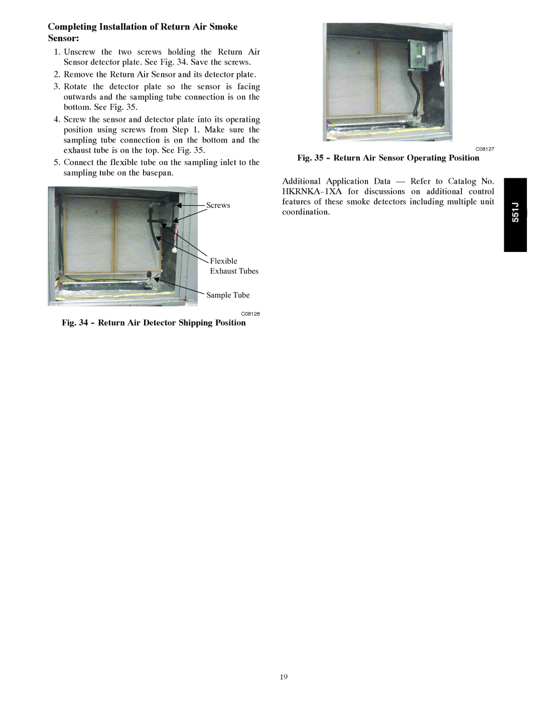
1.Unscrew the two screws holding the Return Air Sensor detector plate. See Fig. 34. Save the screws.
2.Remove the Return Air Sensor and its detector plate.
3.Rotate the detector plate so the sensor is facing outwards and the sampling tube connection is on the bottom. See Fig. 35.
4.Screw the sensor and detector plate into its operating position using screws from Step 1. Make sure the sampling tube connection is on the bottom and the exhaust tube is on the top. See Fig. 35.
5.Connect the flexible tube on the sampling inlet to the sampling tube on the basepan.
![]() Screws
Screws
Flexible
Exhaust Tubes
Sample Tube
C08126
Fig. 34 - Return Air Detector Shipping Position
C08127
Fig. 35 - Return Air Sensor Operating Position
Additional Application Data — Refer to Catalog No.
551J
j
19