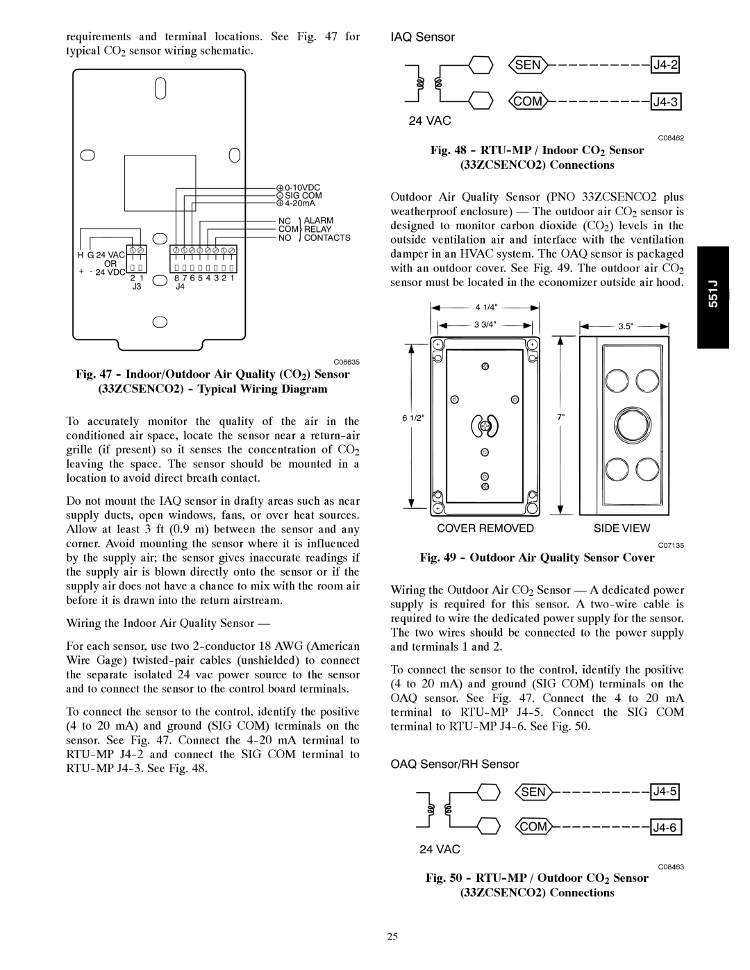
requirements and terminal locations. See Fig. 47 for typical CO2 sensor wiring schematic.
IAQ Sensor |
|
SEN | |
COM | |
24 VAC |
|
| C08462 |
Fig. 48 - |
|
(33ZCSENCO2) Connections |
|
H G 24 VAC OR
+ - 24 VDC
+
- SIG COM +
NC }ALARM
COM RELAY
NO CONTACTS
2 1 8 7 6 5 4 3 2 1
J3 J4
C08635
Outdoor Air Quality Sensor (PNO 33ZCSENCO2 plus |
|
|
weatherproof enclosure) — The outdoor air CO2 sensor is |
|
|
designed to monitor carbon dioxide (CO2) levels in the |
|
|
outside ventilation air and interface with the ventilation |
|
|
damper in an HVAC system. The OAQ sensor is packaged |
|
|
with an outdoor cover. See Fig. 49. The outdoor air CO2 |
|
|
sensor must be located in the economizer outside air hood. | 551J | j |
| ||
|
|
Fig. 47 - Indoor/Outdoor Air Quality (CO2) Sensor
(33ZCSENCO2) - Typical Wiring Diagram
To accurately monitor the quality of the air in the conditioned air space, locate the sensor near a
Do not mount the IAQ sensor in drafty areas such as near supply ducts, open windows, fans, or over heat sources. Allow at least 3 ft (0.9 m) between the sensor and any corner. Avoid mounting the sensor where it is influenced by the supply air; the sensor gives inaccurate readings if the supply air is blown directly onto the sensor or if the supply air does not have a chance to mix with the room air before it is drawn into the return airstream.
Wiring the Indoor Air Quality Sensor —
For each sensor, use two
To connect the sensor to the control, identify the positive (4 to 20 mA) and ground (SIG COM) terminals on the sensor. See Fig. 47. Connect the
COVER REMOVED | SIDE VIEW |
C07135
Fig. 49 - Outdoor Air Quality Sensor Cover
Wiring the Outdoor Air CO2 Sensor — A dedicated power supply is required for this sensor. A
To connect the sensor to the control, identify the positive (4 to 20 mA) and ground (SIG COM) terminals on the OAQ sensor. See Fig. 47. Connect the 4 to 20 mA terminal to
OAQ Sensor/RH Sensor
SEN 
J4-5
COM 
J4-6
24 VAC
C08463
Fig. 50 - RTU-MP / Outdoor CO2 Sensor
(33ZCSENCO2) Connections
25