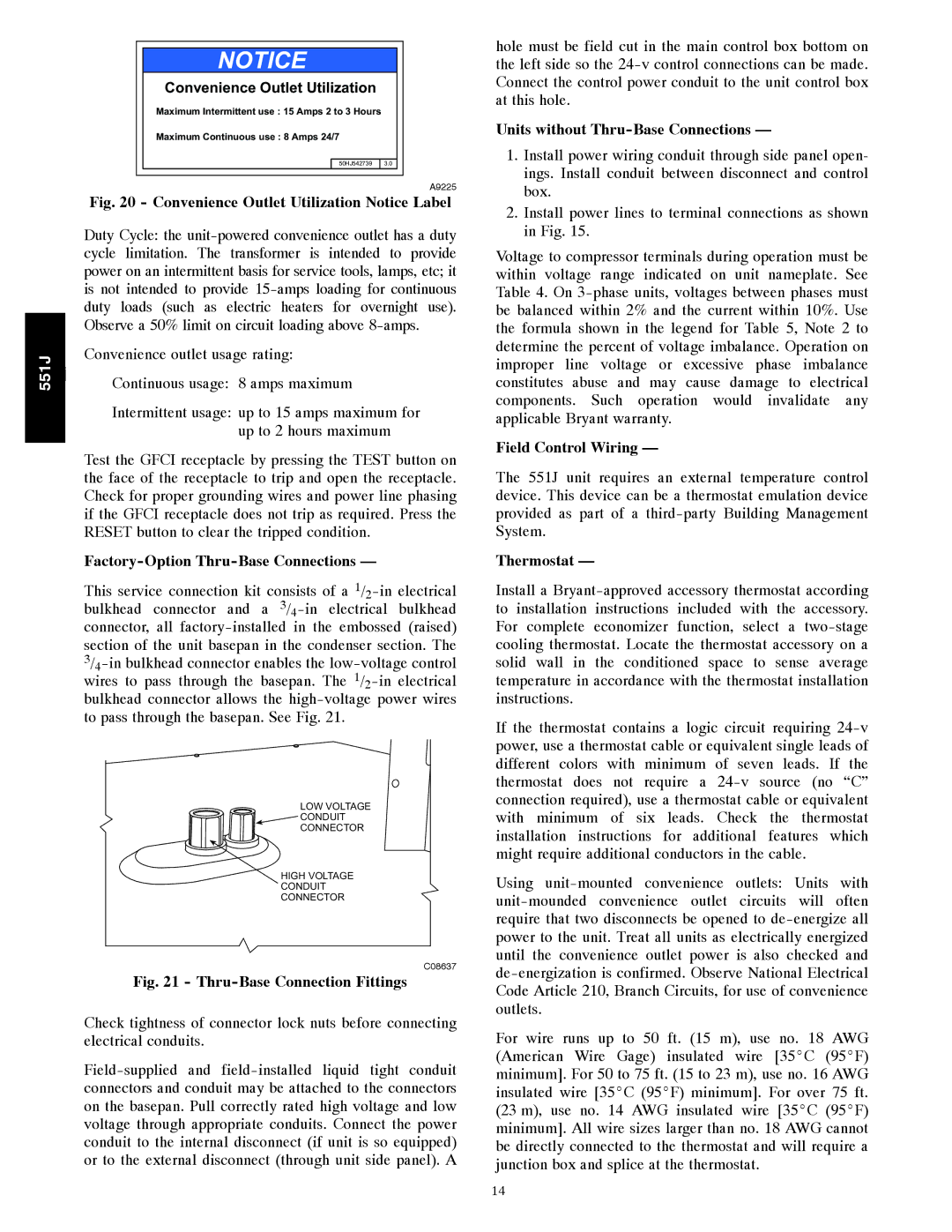
NOTICE
Convenience Outlet Utilization
Maximum Intermittent use : 15 Amps 2 to 3 Hours
Maximum Continuous use : 8 Amps 24/7
|
|
|
|
|
| 50HJ542739 | 3.0 |
|
|
|
|
|
|
|
|
|
|
| A9225 |
|
|
|
|
|
|
|
|
| |
|
|
| Fig. 20 - Convenience Outlet Utilization Notice Label | ||||||
|
|
| Duty Cycle: the | ||||||
|
|
| cycle limitation. The transformer is intended to provide | ||||||
|
|
| power on an intermittent basis for service tools, lamps, etc; it | ||||||
|
|
| is not intended to provide | ||||||
|
|
| duty loads (such as electric heaters for overnight use). | ||||||
|
|
| Observe a 50% limit on circuit loading above | ||||||
551J | j | Convenience outlet usage rating: |
|
|
| ||||
Continuous usage: 8 amps maximum |
|
|
| ||||||
|
|
| Intermittent usage: up to 15 amps maximum for | ||||||
|
|
|
|
| up to 2 hours maximum | ||||
|
|
| Test the GFCI receptacle by pressing the TEST button on | ||||||
|
|
| the face of the receptacle to trip and open the receptacle. | ||||||
|
|
| Check for proper grounding wires and power line phasing | ||||||
|
|
| if the GFCI receptacle does not trip as required. Press the | ||||||
|
|
| RESET button to clear the tripped condition. |
|
|
| |||
|
|
|
|
|
|
| |||
|
|
| This service connection kit consists of a | ||||||
|
|
| bulkhead connector and a | ||||||
|
|
| connector, all | ||||||
|
|
| section of the unit basepan in the condenser section. The | ||||||
|
|
| |||||||
|
|
| wires to pass through the basepan. The | ||||||
|
|
| bulkhead connector allows the | ||||||
|
|
| to pass through the basepan. See Fig. 21. |
|
|
| |||
LOW VOLTAGE
![]() CONDUIT
CONDUIT
CONNECTOR
HIGH VOLTAGE
CONDUIT
CONNECTOR
C08637
Fig. 21 - Thru-Base Connection Fittings
Check tightness of connector lock nuts before connecting electrical conduits.
hole must be field cut in the main control box bottom on the left side so the
Units without Thru-Base Connections —
1.Install power wiring conduit through side panel open- ings. Install conduit between disconnect and control box.
2.Install power lines to terminal connections as shown in Fig. 15.
Voltage to compressor terminals during operation must be within voltage range indicated on unit nameplate. See Table 4. On
Field Control Wiring —
The 551J unit requires an external temperature control device. This device can be a thermostat emulation device provided as part of a
Thermostat —
Install a
If the thermostat contains a logic circuit requiring
Using
For wire runs up to 50 ft. (15 m), use no. 18 AWG (American Wire Gage) insulated wire [35_C (95_F) minimum]. For 50 to 75 ft. (15 to 23 m), use no. 16 AWG insulated wire [35_C (95_F) minimum]. For over 75 ft. (23 m), use no. 14 AWG insulated wire [35_C (95_F) minimum]. All wire sizes larger than no. 18 AWG cannot be directly connected to the thermostat and will require a junction box and splice at the thermostat.
14