Manuals
/
Bryant
/
Household Appliance
/
Fan
Bryant
551J
installation instructions
RTU-MP System Control Wiring Diagram
Models:
551J
1
21
36
36
Download
36 pages
21.67 Kb
18
19
20
21
22
23
24
25
Install
Field Control Wiring
Dimension
Local Access
Heat Anticipator Settings
Space Temperature SPT Sensors
Weight
Field Power Supply
EconoMi$er IV Occupancy Switch
Page 21
Image 21
551J
j
C10044
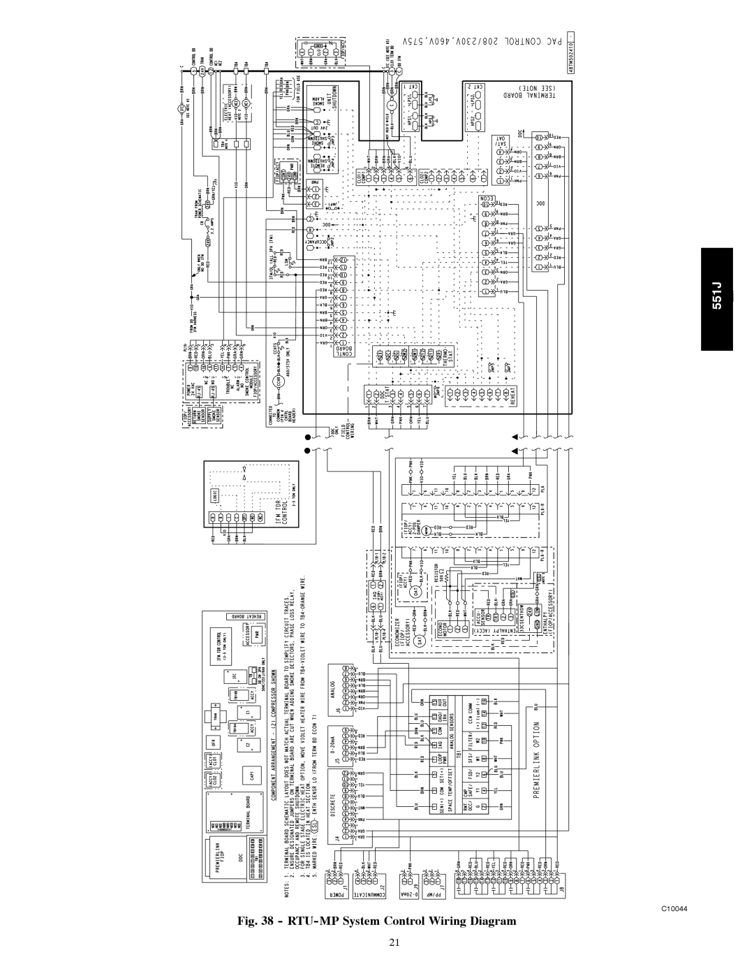
Fig. 38 -
RTU-MP
System Control Wiring Diagram
21
Page 20
Page 22
Page 21
Image 21
Page 20
Page 22
Contents
Installation Instructions
551J
Unit Dimensional Drawing
C10058
Curb-mounted installation
Plan for Sequence of Unit Installation
Operating Weights
Plan for Unit Location
Provide Unit Support
Inspect unit
Roof Curb Details
Rig and Place Unit
Field Fabricate Ductwork
Convert to Horizontal and Connect Ductwork when required
Install Outside Air Hood
Positioning on Curb
Indoor Coil Access Panel Relocation
Install External Condensate Trap and Line
Field Power Supply
Make Electrical Connections
Convenience Outlets
All units
Convenience Outlet Location Installing Weatherproof Cover
Factory-Option Thru-Base Connections
Field Control Wiring
Units without Thru-Base Connections
Thermostat
Heat Anticipator Settings
Electric Heaters
Heater Model Number
Typical Component Location
System
Controller
Smoke Detectors
Typical Supply Air Smoke Detector Sensor Location
Smoke Detector Locations
Return Air Detector Shipping Position
Completing Installation of Return Air Smoke Sensor
RTU-MP Multi-Protocol Control Board
RTU-MP control system
RTU-MP System Control Wiring Diagram
Type of I/O Connection PIN Name Numbers Inputs
RTU-MP Controller Inputs and Outputs
55 Space Temperature Sensor Wiring
Space Temperature SPT Sensors
RTU-MP T-56 Sensor Connections
SEN
Power Exhaust output
Connecting Discrete Inputs
Communication Wiring Protocols General
Filter Status
RTU-MP Troubleshooting Communication LEDs
Local Access
LEDs on the RTU-MP show the status of certain functions
LEDs
FLA LRA
Unit Wire/Fuse or Hacr Breaker Sizing Data
Pwrd C.O
27.8
132
42.0
47/47
EconoMi$er IV Occupancy Switch
Adjust Factory-Installed Options
Pre-Start and Start-Up
Install Accessories
Top
Page
Image
Contents