551J
Table 3 – RTU-MP Controller Inputs and Outputs
|
|
| POINT NAME | BACnet OBJECT |
| TYPE OF I/O | CONNECTION PIN |
|
|
| NAME |
| NUMBERS | ||
|
|
|
|
|
| ||
|
|
|
|
|
|
|
|
|
|
|
| INPUTS |
|
| |
|
|
|
|
|
| ||
| Space Temperature Sensor | sptsens |
| AI (10K Thermistor) | |||
|
|
|
|
|
| ||
| Supply Air Temperature | sat |
| AI (10K Thermistor) | |||
|
|
|
|
|
| ||
| Local Outside Air Temperature Sensor | oatsens |
| AI (10K Thermistor) | |||
|
|
|
|
|
| ||
| Space Temperature Offset Pot | sptopot |
| AI (100K Potentiometer) | |||
|
|
|
|
|
| ||
| Indoor Air Quality | iaq |
| AI | |||
|
|
|
|
|
| ||
| Outdoor Air Quality | oaq |
| AI | |||
|
|
|
|
|
| ||
| Safety Chain Feedback | safety |
| DI (24 VAC) | |||
|
|
|
|
|
| ||
| Compressor Safety | compstat |
| DI (24 VAC) | |||
|
|
|
|
|
| ||
| Fire Shutdown | firedown |
| DI (24 VAC) | |||
|
|
|
|
|
| ||
| Enthalpy Switch | enthalpy |
| DI (24 VAC) | |||
|
|
|
|
|
| ||
j | Humidistat Input Status | humstat |
| DI (24 VAC) | |||
|
|
|
|
|
|
| |
|
|
| CONFIGURABLE INPUTS* |
| |||
|
|
|
|
| |||
|
|
|
|
| |||
| Space Relative Humidity | sprh |
| AI | |||
|
|
|
|
|
|
| |
| Outside Air Relative Humidity | oarh |
| AI | |||
|
|
| |||||
|
|
|
|
|
| ||
| Supply Fan Status | fanstat |
| DI (24 VAC) | |||
|
|
|
|
|
|
| |
| Filter Status | filtstat |
| DI (24 VAC) | |||
|
| J5 5,6 or | |||||
|
|
|
|
|
|
| |
| Remote Occupancy Input | remocc |
| DI (24 VAC) | |||
|
|
| |||||
|
|
|
|
|
|
|
|
|
|
|
| OUTPUTS |
|
| |
|
|
|
|
| |||
| Economizer Commanded Position | econocmd |
| ||||
|
|
|
|
|
| ||
| Supply Fan Relay State | sf |
| DO Relay (24VAC , 1A) | |||
|
|
|
|
|
| ||
| Compressor 1 Relay State | comp_1 |
| DO Relay (24VAC , 1A) | |||
|
|
|
|
|
| ||
| Compressor 2 Relay State | comp_2 |
| DO Relay (24VAC , 1A) | |||
|
|
|
|
|
| ||
| Heat Stage 1 Relay State | heat_1 |
| DO Relay (24VAC , 1A) | |||
|
|
|
|
|
| ||
| Heat Stage 2 Relay State | heat_2 |
| DO Relay (24VAC , 1A) | |||
|
|
|
|
|
| ||
| Power Exhaust Relay State | aux_2 |
| DO Relay (24VAC , 1A) | |||
|
|
|
|
|
| ||
| Dehumidification Relay State | humizer |
| DO Relay (24VAC, 1A) | |||
|
|
|
|
|
| ||
| LEGEND |
|
|
|
| ||
| AI | Analog Input |
|
|
|
| |
| AO | Analog Output |
|
|
|
| |
| DI | Discrete Input |
|
|
|
| |
| DO | Discrete Output |
|
|
|
| |
*These inputs (if installed) take the place of the default input on the specific channel according to schematic. Parallel pins
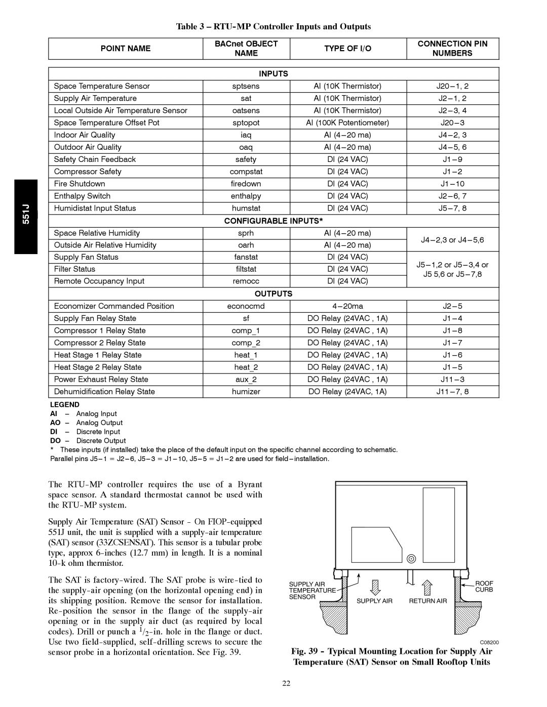
The
Supply Air Temperature (SAT) Sensor - On
The SAT is
SUPPLY AIR TEMPERATURE
SENSOR
SUPPLY AIR
ROOF CURB
RETURN AIR
C08200
sensor probe in a horizontal orientation. See Fig. 39.
Fig. 39 - Typical Mounting Location for Supply Air Temperature (SAT) Sensor on Small Rooftop Units
22