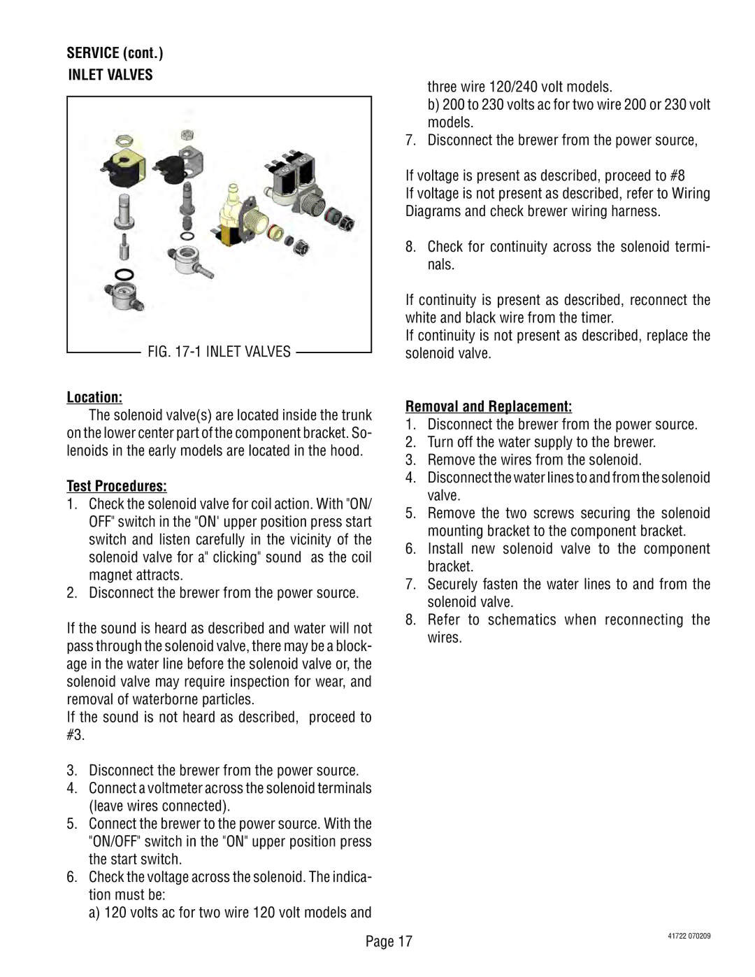
SERVICE (cont.) |
|
|
|
| |||
INLET VALVES |
|
|
| three wire 120/240 volt models. | |||
|
|
|
|
|
| ||
|
|
|
|
|
| b) 200 to 230 volts ac for two wire 200 or 230 volt | |
|
|
|
|
|
| models. | |
|
|
|
|
| 7. | Disconnect the brewer from the power source, | |
|
|
|
|
| If voltage is present as described, proceed to #8 | ||
|
|
|
|
| If voltage is not present as described, refer to Wiring | ||
|
|
|
|
| Diagrams and check brewer wiring harness. | ||
|
|
|
|
| 8. | Check for continuity across the solenoid termi- | |
|
|
|
|
|
| nals. | |
|
|
|
|
| If continuity is present as described, reconnect the | ||
|
|
|
|
| white and black wire from the timer. | ||
|
|
|
|
| If continuity is not present as described, replace the | ||
| FIG. |
|
|
| |||
|
|
|
| solenoid valve. | |||
|
|
|
| ||||
Location: |
|
| Removal and Replacement: | ||||
The solenoid valve(s) are located inside the trunk | |||||||
1. | Disconnect the brewer from the power source. | ||||||
on the lower center part of the component bracket. So- | |||||||
2. | Turn off the water supply to the brewer. | ||||||
lenoids in the early models are located in the hood. | |||||||
3. | Remove the wires from the solenoid. | ||||||
|
|
|
|
| |||
Test Procedures: |
|
| 4. | Disconnect the water lines to and from the solenoid | |||
|
|
| valve. | ||||
1. Check the solenoid valve for coil action. With "ON/ |
| ||||||
5. | Remove the two screws securing the solenoid | ||||||
OFF" switch in the "ON' upper position press start | |||||||
| mounting bracket to the component bracket. | ||||||
switch and listen carefully in the vicinity of the |
| ||||||
6. | Install new solenoid valve to the component | ||||||
solenoid valve for a" clicking" sound | as the coil | ||||||
| bracket. | ||||||
magnet attracts. |
|
|
| ||||
|
| 7. | Securely fasten the water lines to and from the | ||||
2. Disconnect the brewer from the power source. | |||||||
| solenoid valve. | ||||||
|
|
|
|
|
| ||
If the sound is heard as described and water will not | 8. | Refer to schematics when reconnecting the | |||||
| wires. | ||||||
pass through the solenoid valve, there may be a block- |
| ||||||
|
| ||||||
age in the water line before the solenoid valve or, the |
|
| |||||
solenoid valve may require inspection for wear, and |
|
| |||||
removal of waterborne particles. |
|
|
|
| |||
If the sound is not heard as described, | proceed to |
|
| ||||
#3. |
|
|
|
|
|
| |
3. Disconnect the brewer from the power source.
4. Connect a voltmeter across the solenoid terminals (leave wires connected).
5. Connect the brewer to the power source. With the "ON/OFF" switch in the "ON" upper position press the start switch.
6. Check the voltage across the solenoid. The indica- tion must be:
a) 120 volts ac for two wire 120 volt models and
Page 17 | 41722 070209 |
|
